50 & 20 Years Ago
Composite Construction for Crown Office Block at Hastings
 From Building with Steel August 1965
This is an ambitious building plan aimed at removing 800 staff from congested London to the more salubrious air of Hastings. The project has been designed by the Ministry of Public Building and Works, through its Senior Architect, E. H. Banks, F.R.I.B.A., F.R.S.A. and Project Architect, E. B. Power, D.S.C..
The buildings have been planned on a fully industrialised basis; factory-made units are being used on a large scale and the whole of the site operations are so co-ordinated that the contract will be completed in only sixteen months. The advantages and speed of the plan were outlined by the Ministry’s Directory of Works in the course of an address made to a large gathering of Architects and Consulting Engineers visiting the site at the invitation of the B.C.S.A.
In addition to five storey offices, there will be a single-storey block which will have a data preparation unit and three electronic computers, together with the attendant air conditioning plant.
The structural design and development of this project arise out of the Ministry’s current efforts to encourage the use of industrialised methods in building, in all forms of construction.
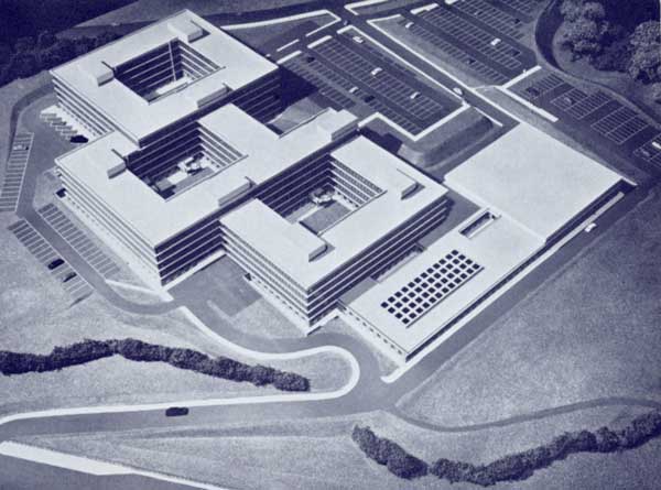
The buildings are all based on an 18 ft. square grid and the five storey offices are in two interlocking hollow rectangular blocks, staggered in plan, in which each side of the rectangles is two units of 18 ft. wide. The dimensions on the outside are approximately 180 ft. × 162 ft. (10 units × 9 units) so that the enclosed glassed and paved courtyard is about 108 ft. × 90 ft. The natural slope of the ground has made it convenient to have one block and its courtyard one storey higher than the other, so that where the upper block overlaps the lower one the building becomes one of six storeys. Should a further block be constructed in the future on the eastern side, and provision is made for this, it will again be stepped up one storey, as shown in the illustration of the model. The computer block adjoins the lower office block on its western side.
 Structural Design
Studies between the Ministry and the British Constructional Steelwork Association have concluded that an economic structure for office building can be obtained using a steel frame in which the concrete floors act compositely with the steel beams and by adopting lightweight dry board casings for fire protection.
This new Crown Office building has been designed on this basis although fire protection of the beams is achieved by using a suspended ceiling which additionally facilitates re-siting of partitions, housing of services and provides a permanent finish.
The lateral forces imposed on the structure are transmitted by the concrete floors to the r.c. walls enclosing the staircase and lift well units. The units provide the strong points through which the lateral forces are resisted and transferred to the ground.
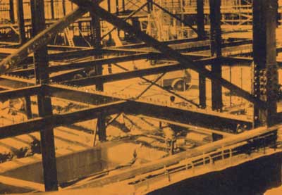
The frame consists of steelwork arranged on the 18 ft. square grid, with intermediate floor beams at 9 ft. centres. The design is such as to keep the number of different sections, lengths and details to a minimum. Stanchions generally are of 8 in. × 8 in. UC sections varying in weight from 58 lb. per ft. to 31 lb. per ft. In a few instances these are cased in concrete where architectural or fire requirements demand this treatment. Where the top length of stanchion is a single storey height, the section is reduced to 6 in × 6 in. UC at 15.7 lb.
Stanchion bases are of four types but all have the same size holding down bolts at standard centres. The beams for the multi-storey blocks are mainly of three sections, 8 in. × 8 in. UC at 31 lb. at all perimeter positions, with 10 in. × 5¾ in. UB at 29 lb. and 7 in. × 4 in. joists at 14.5 lb internally. Intermediate 7 in. × 4 in. joists spanning between the 10 in. × 5¾ in. UBs divide the floor slabs into 9 ft. spans. Site connections are made with black bolts.
Internal beams connecting to stanchions have a shop welded top cleat and are supported on bearing cleats welded to the stanchions. Beam-to-beam connections are made through packs on the bottom flanges of the deeper beams. The external 8 in. × 8 in. beams are bolted through their webs direct to stanchion flanges.
The single-storey computer block generally is in two sections, one of 10 ft. 6 in. storey height in which the steelwork is similar to that in the five-storey blocks and the other with its roof level 19 ft. 3 in. above the floor. In this high section, main internal beams span 54 ft. and 36 ft. and are castellated sections 36 in. and 27 in. deep respectively. Secondary roof beams are 7 in. × 4 in. joists internally and 8 in. × 8 in. UC sections around the perimeter. Additional perimeter beams (8 in. × 5¼ in. UB at 20 lb.) at low level help support the cladding.
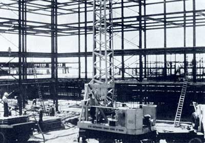
Close integration of work between the steelwork and main contractors is achieved by the planned release of the steel framework in sections. This involves the use of temporary bracing to enable each section to be plumbed and levelled and rendered stable to enable the main contractor to follow closely behind the steelwork erectors. The temporary braces remain in position until the concrete floors have been joined to the r.c. walls of the staircase and lift blocks which provide the necessary stability against lateral forces.
 Both floors and roof are formed from 2 in. thick prestressed concrete planks with a 2 in. in situ reinforced concrete structural topping. The topping for the floors is given a smooth finish so that floor covering can be laid direct; no screed is required. Roof slabs are screeded to falls for drainage purposes and finished with asbestos tiles. The slabs are designed to act compositely with the beams which have ½ in. diameter stud shear connectors shop welded to the top flange. At the perimeters, both on the external face and on the side of the courtyard, the floor and roof slabs cantilever over the 8 in. × 8 in. UC beams to carry precast concrete cill and parapet units, the other faces of which are 2 ft. 3 in. beyond the 18 ft. grid line.
Staircases and lifts are generally sited at internal corners to give direct emergency access to the courtyards. The staircases are formed of hardwood treads and landings, mounted on steel plates welded to a central stringer of 8 in. × 8in. hollow section.
Cladding
The elevations, both external and courtyard, are treated in a uniform manner to afford the greatest amount of repetition of off-site fabrication.
Except for the bottom storey, the office blocks are enclosed by a screen of floor to ceiling hardwood framed window units with connecting mullions. The standard window frame width is 4 ft. 6 in. to fit in with the square grid of 18 ft. and the frames are fixed sufficiently outside the stanchion centre to permit heaters, ring mains and telephone circuits to pass behind the columns. The elevation of the bottom storeys is finished with precast exposed aggregate panels, cramped back to 9 in. concrete block walls which, being external to the steel columns, are entirely independent of the structural frame. Erection of the steelwork and building of all main structural walls and staircase blocks may thus proceed independently.