Cold formed sections
Cold formed sections
The forming process affects the toughness of cold formed sections and their use in external
structures. Welding is prohibited near the corners of cold formed sections in certain
circumstances. Richard Henderson of the SCI discusses the issues.
The toughness of steel is affected by the extent of strain it has undergone
as well as by other factors. This fact is taken into account when determining
the limiting thickness for materials using BS EN 1993-1-10. The limiting
thickness of plate or hot rolled or hot finished structural sections does
not, in general, depend on the extent of strain because such elements
are not subject to plastic strain during their use, nor in the course of their
manufacture. This does not apply however to cold formed square and
rectangular hollow sections, which experience significant strains at the
corners of the profile. Neither does it apply to beams which have been precambered
The product standard for cold formed welded structural hollow sections,
BS EN 10219-1:2006 requires that for square or rectangular sections, the
test pieces for impact testing are taken either longitudinally or transversely
midway between the corners from one of the sides not containing the weld.
The impact values therefore relate to material which is unaffected by cold
forming, thus tacitly acknowledging that the forming process affects the
material toughness. According to clause 6.7.2 of the product standard, there
is no requirement for impact tests for specified thicknesses of less than 6
mm.
The effect of strain during cold forming must be taken into account
when determining the limiting thickness of material of a given sub-grade.
According to BS EN 1993-1-10 and its UK National Annex, the reference
temperature TEd for determining the toughness of a steel element:
TEd = Tmd + Tr + T + TR + T + Tcf
where (Tmd+ΔTr) considered together represent the minimum effective
temperature of the steel part, ΔTR is a safety allowance, ΔTε is an adjustment
for strain rate and ΔTεcf
forming.
The UK National Annex collects together factors affecting the safety of
elements and gives an equation for ΔTR as follows:
6 NSC
by cold bending.
is an adjustment for the extent of strain during cold
Technical Digest 2018
TR = TRD + TRg + TRT + TR + TRs
where ΔTRD is an adjustment for detail type, ΔTRg for gross stress
concentration, ΔTRT for Charpy test temperature, ΔTRσ for stress level and ΔTRs
for strength grade. The procedure is consistent with ΔTσ = 0.
The temperature adjustment for cold forming is given in clause 2.3.1(2)
of the standard as minus three times the percentage strain expressed as
degrees Celsius. A strain of 10% would result in a temperature adjustment of
−30 °C. This is potentially significant when considering the adoption of cold
formed sections.
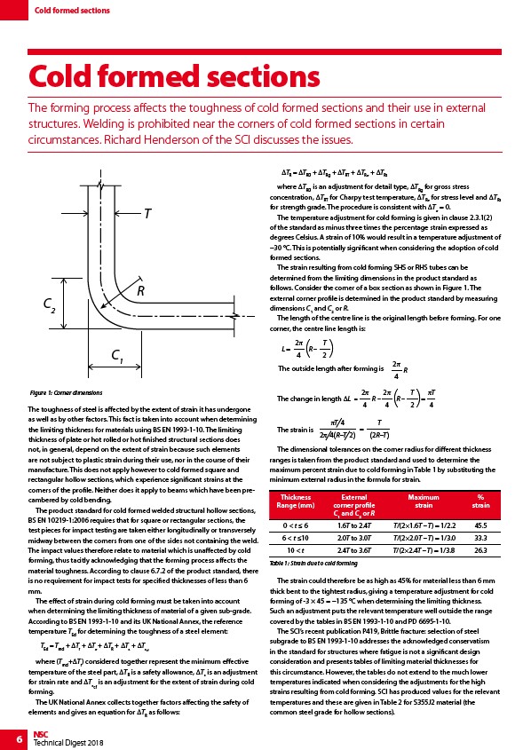
The strain resulting from cold forming SHS or RHS tubes can be
determined from the limiting dimensions in the product standard as
follows. Consider the corner of a box section as shown in Figure 1. The
external corner profile is determined in the product standard by measuring
dimensions C1 and C2 or R.
The length of the centre line is the original length before forming. For one
corner, the centre line length is:
L =
2
4
( T
R –
)
2 The outside length after forming is
2
4
R
The change in length ΔLL =
2
4
R –
T
4
2
4
( T
R –
)=
2
L
L
=
The strain is
T 4
2 4(R–T 2)
=
T
(2R–T)
The dimensional tolerances on the corner radius for different thickness
ranges is taken from the product standard and used to determine the
maximum percent strain due to cold forming in Table 1 by substituting the
minimum external radius in the formula for strain.
The strain could therefore be as high as 45% for material less than 6 mm
thick bent to the tightest radius, giving a temperature adjustment for cold
forming of -3 × 45 = −135 °C when determining the limiting thickness.
Such an adjustment puts the relevant temperature well outside the range
covered by the tables in BS EN 1993-1-10 and PD 6695-1-10.
The SCI’s recent publication P419, Brittle fracture: selection of steel
subgrade to BS EN 1993-1-10 addresses the acknowledged conservatism
in the standard for structures where fatigue is not a significant design
consideration and presents tables of limiting material thicknesses for
this circumstance. However, the tables do not extend to the much lower
temperatures indicated when considering the adjustments for the high
strains resulting from cold forming. SCI has produced values for the relevant
temperatures and these are given in Table 2 for S355J2 material (the
common steel grade for hollow sections).
Figure 1: Corner dimensions
T
R
C2
C1
Thickness
Range (mm)
External
corner profile
C1 and C2 or R
Maximum
strain
%
strain
0 < t ≤ 6 1.6T to 2.4T T/(2×1.6T – T) = 1/2.2 45.5
6 < t ≤10 2.0T to 3.0T T/(2×2.0T – T) = 1/3.0 33.3
10 < t 2.4T to 3.6T T/(2×2.4T – T) = 1/3.8 26.3
Table 1: Strain due to cold forming