Bridges
NSC 15
Technical Digest 2018
requirement and our understanding is that the torsional restraint is effective
because of the u-frame action.
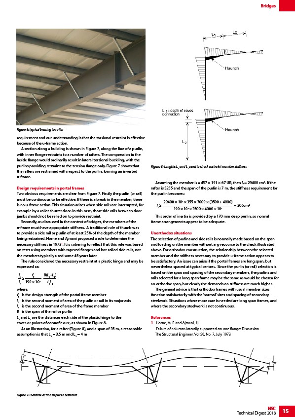
A section along a building is shown in Figure 7, along the line of a purlin,
with inner flange restraints to a number of rafters. The compression in the
inside flange would ordinarily result in lateral torsional buckling, with the
purlins providing restraint to the tension flange only. Figure 7 shows that
the rafters are restrained with respect to the purlin, forming an inverted
u-frame.
Design requirements in portal frames
Two obvious requirements are clear from Figure 7. Firstly the purlin (or rail)
must be continuous to be effective. If there is a break in the member, there
is no u-frame action. This situation arises when side rails are interrupted, for
example by a roller shutter door. In this case, short side rails between door
jambs should not be relied on to provide restraint.
Secondly, as discussed in the context of bridges, the members of the
u-frame must have appropriate stiffness. A traditional rule of thumb was
to provide a side rail or purlin of at least 25% of the depth of the member
being restrained. Horne and Ajmani proposed a rule to determine the
necessary stiffness in 19731. It is sobering to reflect that this rule was based
on tests using members with tapered flanges and hot-rolled side rails, not
the members typically used some 45 years later.
The rule considered the necessary restraint at a plastic hinge and may be
expressed as:
IB(L+L)
s
12ILLf
12
where,
fy is the design strength of the portal frame member
Is is the second moment of area of the purlin or rail in its major axis
If is the second moment of area of the frame member
B is the span of the rail or purlin
L1 and L2 are the distances each side of the plastic hinge to the
eaves or points of contraflexure, as shown in Figure 8.
As an illustration, for a rafter (Figure 8), and a span of 35 m, a reasonable
assumption is that L1 = 3.5 m and L2 = 4 m
fy
190 × 103
Assuming the member is a 457 × 191 × 67 UB, then If = 29400 cm4. If the
rafter is S355 and the span of the purlin is 7 m, the stiffness requirement for
the purlin becomes:
Is
29400 × 104 × 355 × 7000 × (3500 + 4000)
190 × 103 × 3500 × 4000 × 104
= 206cm4
This order of inertia is provided by a 170 mm deep purlin, so normal
frame arrangements appear to be adequate.
Unorthodox situations
The selection of purlins and side rails is normally made based on the span
and loading on the member without any recourse to the check illustrated
above. For orthodox construction, the relationship between the selected
member and the stiffness necessary to provide u-frame action appears to
be satisfactory. An issue can arise if the portal frames are long span, but
nevertheless spaced at typical centres. Since the purlin (or rail) selection is
based on the span and spacing of the secondary members, the purlins and
rails selected for a long span frame may be the same as would be chosen for
an orthodox span, but clearly the demands on stiffness are much higher.
The general advice is that orthodox frames with usual member sizes
function satisfactorily with the ‘normal’ sizes and spacing of secondary
steelwork. Situations where more care is needed are long span frames, and
where the secondary steelwork is not continuous.
References
1 Horne, M, R and Ajmani, J,L.
Failure of columns laterally supported on one flange: Discussion
The Structural Engineer, Vol 50, No. 7, July 1973
Figure 6: typical bracing to rafter
Figure 7: U-frame action in purlin restraint
Figure 8: Lengths L1 and L2 used to check restraint member stiffness
/Portal_frames
/Bridges
/Member_design#Lateral_torsional_buckling_resistance
/Building_envelopes#Purlin_and_side_rail_options