Buckling
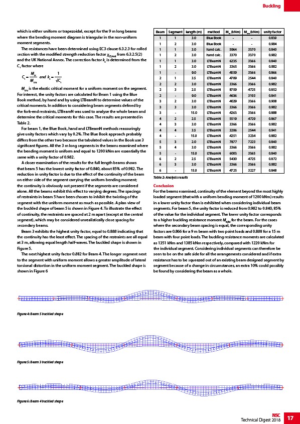
Beam Segment length (m) method Mcr (kNm) Mcru (kNm) unity factor
1 1 3.0 Blue Book - - 0.839
1 2 3.0 Blue Book - - 0.984
1 1 3.0 hand calc. 5964 3370 0.840
1 2 3.0 hand calc. 3370 3370 0.982
1 1 3.0 LTBeamN 6235 3366 0.840
1 2 3.0 LTBeamN 3365 3366 0.982
1 - 9.0 LTBeamN 4559 3366 0.866
2 1 3.5 LTBeamN 4709 2544 0.840
2 2 3.0 LTBeamN 3366 3366 0.982
2 3 2.5 LTBeamN 8759 4725 0.852
2 - 9.0 LTBeamN 4636 3193 0.841
3 2 3.0 LTBeamN 4029 3366 0.908
3 3 3.0 LTBeamN 3366 3366 0.982
3 - 15.0 LTBeamN 4263 3366 0.888
4 2 2.5 LTBeamN 5519 4729 0.867
4 3 3.0 LTBeamN 3366 3366 0.982
4 4 3.5 LTBeamN 3206 2544 0.941
4 - 15.0 LTBeamN 4251 3234 0.882
5 3 2.0 LTBeamN 7877 7223 0.840
5 4 3.0 LTBeamN 3366 3366 0.982
5 - 15.0 LTBeamN 6003 3365 0.840
6 2 2.5 LTBeamN 5430 4725 0.872
6 3 3.0 LTBeamN 3366 3366 0.982
6 - 15.0 LTBeamN 4725 3227 0.848
Table 2: Analysis results
NSC 17
Technical Digest 2018
which is either uniform or trapezoidal, except for the 9 m long beams
where the bending moment diagram is triangular in the non-uniform
moment segments.
The resistances have been determined using EC3 clause 6.3.2.3 for rolled
section with the modified strength reduction factor χLT,mod from 6.3.2.5(2)
and the UK National Annex. The correction factor kc is determined from the
C1 factor where
C1 =
1
C1
Mcr
Mcru
and kc =
Mcru is the elastic critical moment for a uniform moment on the segment.
For interest, the unity factors are calculated for Beam 1 using the Blue
Book method, by hand and by using LTBeamN to determine values of the
critical moments. In addition to considering beam segments defined by
the fork-end restraints, LTBeamN was used to analyse the whole beam and
determine the critical moments for this case. The results are presented in
Table 2.
For beam 1, the Blue Book, hand and LTBeamN methods reassuringly
give unity factors which vary by 0.2%. The Blue Book approach probably
differs from the other two because the tabulated values in the Book use 3
significant figures. All the 3 m long segments in the beams examined where
the bending moment is uniform and equal to 1200 kNm are essentially the
same with a unity factor of 0.982.
A closer examination of the results for the full length beams shows
that beam 5 has the lowest unity factor of 0.840, about 85% of 0.982. The
reduction in unity factor is due to the effect of the continuity of the beam
on either side of the segment carrying the uniform bending moment;
the continuity is obviously not present if the segments are considered
alone. All the beams exhibit this effect to varying degrees. The spacings
of restraints in beam 5 have been chosen to inhibit the twisting of the
segment with the uniform moment as much as possible. A plan view of
the buckled shape of beam 5 is shown in Figure 4. To illustrate the effect
of continuity, the restraints are spaced at 2 m apart (except at the central
segment), which may be considered unrealistically close spacing for
secondary beams.
Beam 3 exhibits the highest unity factor, equal to 0.888 indicating that
the continuity has the least effect. The spacing of the restraints are all equal
at 3 m, allowing equal length half-waves. The buckled shape is shown in
Figure 5.
The next highest unity factor 0.882 for Beam 4. The longer segment next
to the segment with uniform moment allows a greater amplitude of lateral
torsional distortion in the uniform moment segment. The buckled shape is
shown in Figure 6
Conclusion
For the beams examined, continuity of the element beyond the most highly
loaded segment (that with a uniform bending moment of 1200 kNm) results
in a lower unity factor than is exhibited when considering individual beam
segments. For beam 5, the unity factor is reduced from 0.982 to 0.840, 85%
of the value for the individual segment. The lower unity factor corresponds
to a higher buckling resistance moment Mb,Rd for the beam. For the cases
where the secondary beam spacing is equal, the corresponding unity
factors are 0.866 for a 9 m beam with two point loads and 0.888 for a 15 m
beam with four point loads. The buckling resistance moments are calculated
as 1351 kNm and 1385 kNm respectively, compared with 1220 kNm for
the individual segment. Considering individual segments can therefore be
seen to be on the safe side for all the arrangements considered and if extra
resistance has to be squeezed out of an existing beam designed segment by
segment because of a change in circumstances, an extra 10% could possibly
be found by considering the beam as a whole.
Figure 4: Beam 5 buckled shape
Figure 5: Beam 3 buckled shape
Figure 6: Beam 4 buckled shape