Composite beams
Composite beam design at elevated
temperature: comparisons between
different temperature distributions in
the concrete flange
Several resources give guidance on the temperature profile through composite slabs; BS 5950-8,
EN 1994-1-2 and NCCI PN005C-GB. Ricardo Pimentel of the SCI discusses the impact of these
alternative profiles on the design of composite beams at elevated temperature.
Composite beams are one of the most common structural elements in the
UK construction market. Steel and concrete are connected by mechanical
devices (shear connection – usually studs), allowing the two materials to
work together. Composite beams are usually simply supported elements,
allowing the steel to be mainly in tension and the concrete in compression.
The fire design of composite beams is often required, which demands
an assessment of resistance of the concrete, steel and studs at elevated
temperature. The main topic of this article is to evaluate the impact of
alternative temperature distributions in the slab to obtain the critical
temperature or the allowable fire exposure period of composite beams.
For a composite beam design at elevated temperature, there are three
possible ways to model the temperature distribution in the slab in the
UK: (i) EN 1994-1-21 Annex D Table D.5; (ii) BS 5950-82 Table 12; (iii) NCCI
PN005C-GB3. However, note that the UK National Annex to EN 1994-1-24
states that Annex D should not be
used, recommending the use of
non-contradictory complementary
information (NCCI).
The effect of different
temperature profiles will be
assessed based on two worked
examples, comprising 6 m and 12 m
span beams, both optimized for
an adequate performance under
Serviceability Limit States, Ultimate
Limit States and Fire Design. The
geometry and design conditions
for the two worked examples are
summarized in the data presented
in Figure 1 and Table 1.
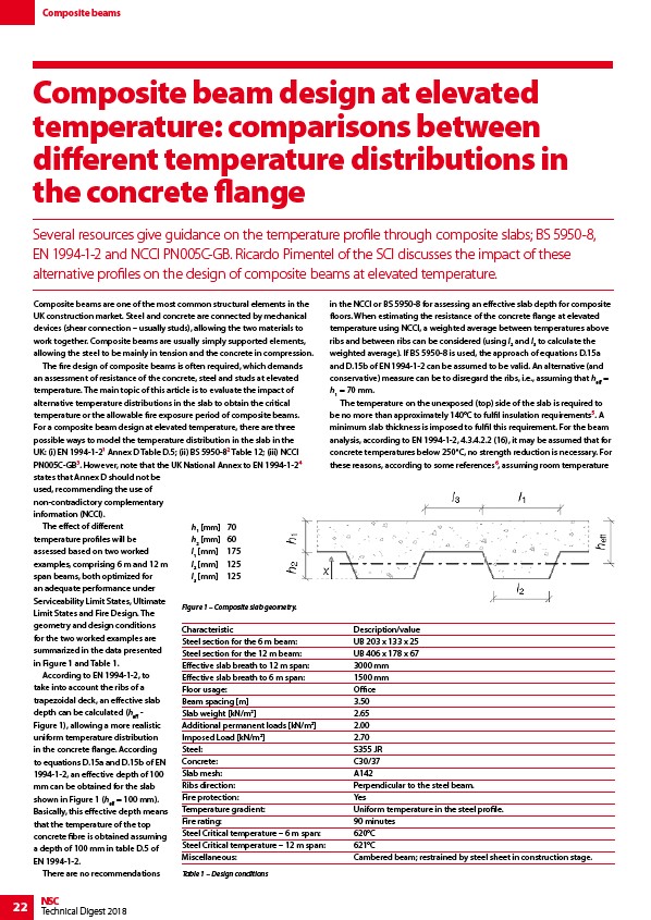
According to EN 1994-1-2, to
take into account the ribs of a
trapezoidal deck, an effective slab
depth can be calculated (heff -
Figure 1), allowing a more realistic
uniform temperature distribution
in the concrete flange. According
to equations D.15a and D.15b of EN
1994-1-2, an effective depth of 100
mm can be obtained for the slab
shown in Figure 1 (heff = 100 mm).
Basically, this effective depth means
that the temperature of the top
concrete fibre is obtained assuming
a depth of 100 mm in table D.5 of
EN 1994-1-2.
There are no recommendations
22 NSC
Technical Digest 2018
in the NCCI or BS 5950-8 for assessing an effective slab depth for composite
floors. When estimating the resistance of the concrete flange at elevated
temperature using NCCI, a weighted average between temperatures above
ribs and between ribs can be considered (using l2 and l3 to calculate the
weighted average). If BS 5950-8 is used, the approach of equations D.15a
and D.15b of EN 1994-1-2 can be assumed to be valid. An alternative (and
conservative) measure can be to disregard the ribs, i.e., assuming that heff =
h1 = 70 mm.
The temperature on the unexposed (top) side of the slab is required to
be no more than approximately 140°C to fulfil insulation requirements5. A
minimum slab thickness is imposed to fulfil this requirement. For the beam
analysis, according to EN 1994-1-2, 4.3.4.2.2 (16), it may be assumed that for
concrete temperatures below 250°C, no strength reduction is necessary. For
these reasons, according to some references6, assuming room temperature
h1 mm 70
h2 mm 60
l1 mm 175
l2 mm 125
l3 mm 125
Figure 1 – Composite slab geometry.
Characteristic Description/value
Steel section for the 6 m beam: UB 203 x 133 x 25
Steel section for the 12 m beam: UB 406 x 178 x 67
Effective slab breath to 12 m span: 3000 mm
Effective slab breath to 6 m span: 1500 mm
Floor usage: Office
Beam spacing m 3.50
Slab weight kN/m2 2.65
Additional permanent loads kN/m2 2.00
Imposed Load kN/m2 2.70
Steel: S355 JR
Concrete: C30/37
Slab mesh: A142
Ribs direction: Perpendicular to the steel beam.
Fire protection: Yes
Temperature gradient: Uniform temperature in the steel profile.
Fire rating: 90 minutes
Steel Critical temperature – 6 m span: 620°C
Steel Critical temperature – 12 m span: 621°C
Miscellaneous: Cambered beam; restrained by steel sheet in construction stage.
Table 1 – Design conditions