Advisory Desk 2018
AD 413
Shear resistances of M12 bolts
AD 414:
Slip-resistant connections to
BS EN 1993-1-8
AD 415:
Vertical tying of columns and
column splices
26 NSC
Technical Digest 2018
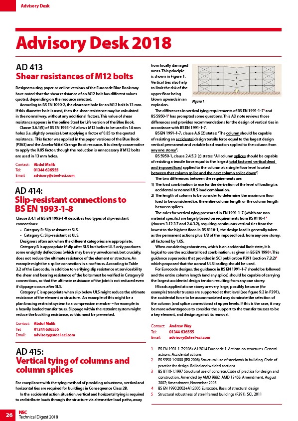
from locally damaged
areas. This principle
is shown in Figure 1.
Vertical ties also help
to limit the risk of the
upper floor being
blown upwards in an
explosion.
The differences in vertical tying requirements of BS EN 1991-1-71 and
BS 5950-12 has prompted some questions. This AD note reviews those
differences and provides recommendations for the design of vertical ties in
accordance with BS EN 1991-1-7.
BS EN 1991-1-7, clause A.6 (2) states: “The column should be capable
of resisting an accidental design tensile force equal to the largest design
vertical permanent and variable load reaction applied to the column from
any one storey”.
BS 5950-1, clause 2.4.5.3 (c) states: “All column splices should be capable
of resisting a tensile force equal to the largest total factored vertical dead
and imposed load applied to the column at a single floor level located
between that column splice and the next column splice down”.
The two differences between the requirements are:
1) The load combination to use for the derivation of the level of loading i.e.
accidental or normal ULS load combination.
2) The length of column to be consider to determine the maximum floor
load to be considered i.e. the entire column length or the column length
between splices.
The rules for vertical tying presented in EN 1991-1-7 (which are nonmaterial
specific) are largely based on requirements from BS 8110-13
(clauses 3.12.3.7 and 2.4.3.2), requiring continuous vertical ties from the
lowest to the highest floor. In BS 8110-1, the design load is generally taken
as the permanent actions plus 1/3 of the imposed load, from any one storey,
all factored by 1.05.
When considering robustness, which is an accidental limit state, it is
logical to use the accidental load combination, as given in BS EN 19904. This
guidance supersedes that provided in SCI publication P391 (section 7.3.2)5
which proposed that the normal ULS loading should be used.
For Eurocode designs, the guidance in BS EN 1991-1-7 should be followed
and the entire column length (and any splice) should be capable of carrying
the largest accidental design tension resulting from any one storey.
If loads applied at one storey are very large, possibly because (for
example) transfer trusses are supported at that level (see figure 9.2 in P391),
the accidental force to be accommodated may dominate the selection of
the column (and splice connections) at upper levels. If this is the case, it may
be more advantageous to consider the support to the transfer trusses to be
a key element, and design against its removal.
Contact: Andrew Way
Tel: 01344 636555
Email: advisory@steel-sci.com
1 BS EN 1991-1-7:2006+A1:2014 Eurocode 1. Actions on structures. General
actions. Accidental actions
2 BS 5950-1:2000 (BSI 2008) Structural use of steelwork in building. Code of
practice for design. Rolled and welded sections
3 BS 8110-1:1997 Structural use of concrete. Code of practice for design and
construction. Amended by AMD 9882, AMD 13468. Amendment, August
2007; Amendment, November 2005
4 BS EN 1990:2002+A1:2005 Eurocode. Basis of structural design
5 Structural robustness of steel framed buildings (P391). SCI, 2011
Designers using paper or online versions of the Eurocode Blue Book may
have noted that the shear resistance of an M12 bolt has different values
quoted, depending on the resource selected.
According to BS EN 1090-2, the clearance hole for an M12 bolt is 13 mm.
If this diameter hole is used, then the shear resistance may be calculated
in the normal way, without any additional factors. This value of shear
resistance appears in the online Steel for Life version of the Blue Book.
Clause 3.6.1(5) of BS EN 1993-1-8 allows M12 bolts to be used in 14 mm
holes (i.e. slightly oversize), but applying a factor of 0.85 to the quoted
resistance. This factor was applied in the paper versions of the Blue Book
(P363) and the ArcelorMittal Orange Book resource. It is clearly conservative
to apply the 0.85 factor, though the reduction is unnecessary if M12 bolts
are used in 13 mm holes.
Contact: Abdul Malik
Tel: 01344 636555
Email: advisory@steel-sci.com
Clause 3.4.1 of BS EN 1993-1-8 describes two types of slip-resistant
connections:
• Category B: Slip-resistant at SLS.
• Category C: Slip-resistant at ULS.
Designers often ask when the different categories are appropriate.
Category B is appropriate if slip after SLS but before ULS only produces
some unsightly deflections (which may be very unwelcome), but crucially,
does not reduce the ultimate resistance of the element or structure. An
example might be a splice connection in a roof truss. According to Table
3.2 of the Eurocode, in addition to verifying slip resistance at serviceability
the shear and bearing resistance of the bolts must be verified in Category B
connections, so that the ultimate resistance of the joint is not reduced even
if slippage occurs after SLS.
Category C is appropriate when slip below ULS might reduce the ultimate
resistance of the element or structure. An example of this might be a
plan bracing restraint system to a compression member – for example in
a heavily loaded transfer truss. Slippage within the restraint system might
reduce the buckling resistance, so this must be prevented.
Contact: Abdul Malik
Tel: 01344 636555
Email: advisory@steel-sci.com
For compliance with the tying method of providing robustness, vertical and
horizontal ties are required for buildings in Consequence Class 2B.
In the accidental action situation, vertical and horizontal tying is required
to redistribute loads through the structure via alternative load paths, away
Figure 1
Advisory Desk
link
link
link