Design checks
NSC 9
=
0.6 (1 + 0.8 )= 0.61
Ncr =
2EI
L2
kyy = 0.6 (1 + (0.276 – 0.2) ) 800
0.6 (1 + 1.4 )= 1.16
kzz = 0.6 (1 + (2 × 1.536 – 0.6) ) 800
kzy = 0.6 (1 – ) = 0.81
(1 – ) 800
Technical Digest 2018
The Blue Book cannot help here, as the expression demands an
intermediate value, λy used as part of the calculation process, but not given in
the tables.
Two options are available for the designer wanting to follow the full process
– calculate the intermediate values needed, or use the graphical presentation
of these interaction factors given in SCI Publication P3621.
Bringing it all together
Designers have options to use simplified versions of these two expressions,
with differing degrees of conservatism. An example of each follows, and then
finally a comparison with the full expression. The comparisons are illustrated
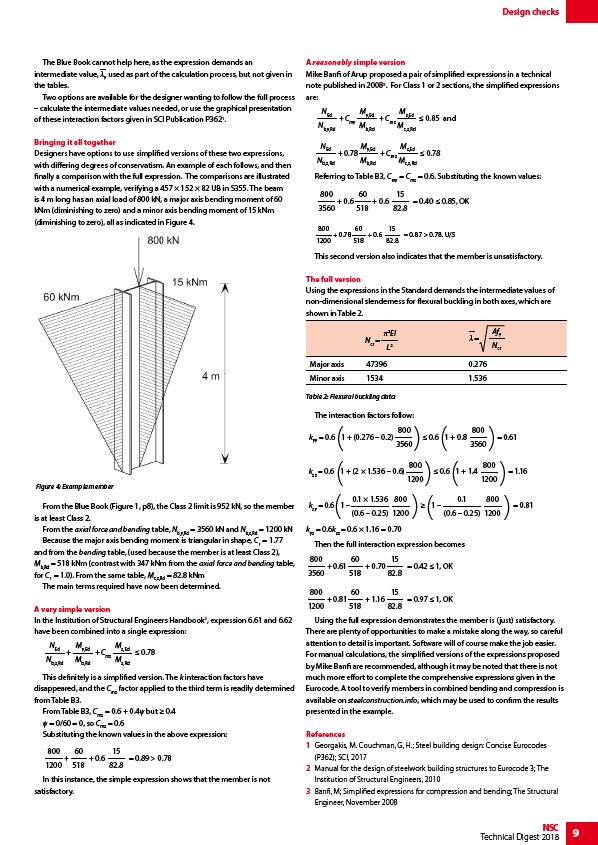
with a numerical example, verifying a 457 × 152 × 82 UB in S355. The beam
is 4 m long has an axial load of 800 kN, a major axis bending moment of 60
kNm (diminishing to zero) and a minor axis bending moment of 15 kNm
(diminishing to zero), all as indicated in Figure 4.
From the Blue Book (Figure 1, p8), the Class 2 limit is 952 kN, so the member
is at least Class 2.
From the axial force and bending table, Nb,y,Rd = 3560 kN and Nb,z,Rd = 1200 kN
Because the major axis bending moment is triangular in shape, C1 = 1.77
and from the bending table, (used because the member is at least Class 2),
Mb,Rd = 518 kNm (contrast with 347 kNm from the axial force and bending table,
for C1 = 1.0). From the same table, Mc,z,Rd = 82.8 kNm
The main terms required have now been determined.
A very simple version
In the Institution of Structural Engineers Handbook2, expression 6.61 and 6.62
have been combined into a single expression:
NEd
Nb,z,Rd
My,Ed
Mb,Rd
+ 0.78
+ Cmz
Mz,Ed
Mz,Rd
This definitely is a simplified version. The k interaction factors have
disappeared, and the Cmz factor applied to the third term is readily determined
from Table B3.
From Table B3, Cmz = 0.6 + 0.4ψ but ≥ 0.4
ψ = 0/60 = 0, so Cmz = 0.6
Substituting the known values in the above expression:
800
1200
60
518
+ = 0.89 > 0.78
+ 0.6
15
82.8
In this instance, the simple expression shows that the member is not
satisfactory.
A reasonably simple version
Mike Banfi of Arup proposed a pair of simplified expressions in a technical
note published in 20083. For Class 1 or 2 sections, the simplified expressions
are:
NEd
Nb,y,Rd
My,Ed
Mb,Rd
+ Cmy 0.85 and
+ Cmz
Mz,Ed
Mc,z,Rd
NEd
Nb,z,Rd
My,Ed
Mb,Rd
+ 0.78 0.78
+ Cmz
Mz,Ed
Mc,z,Rd
Referring to Table B3, Cmy = Cmz = 0.6. Substituting the known values:
800
60
+ 0.6
= 0.40 0.85, OK
3560
518
15
82.8
+ 0.6
800
1200
= 0.87 > 0.78. U/S
60
518
+ 0.6
15
82.8
+ 0.78
This second version also indicates that the member is unsatisfactory.
The full version
Using the expressions in the Standard demands the intermediate values of
non-dimensional slenderness for flexural buckling in both axes, which are
shown in Table 2.
Table 2: Flexural buckling data
The interaction factors follow:
800
3560
3560
800
1200
1200
0.1 × 1.536
(0.6 – 0.25)
800
1200
0.1
(0.6 – 0.25)
1200
kyz = 0.6k= 0.6 × 1.16 = 0.70
zz Then the full interaction expression becomes
800
60
+ 0.70
= 0.42 1, OK
3560
518
15
82.8
+ 0.61
800
1200
= 0.97 1, OK
60
518
+ 1.16
15
82.8
+ 0.81
Using the full expression demonstrates the member is (just) satisfactory.
There are plenty of opportunities to make a mistake along the way, so careful
attention to detail is important. Software will of course make the job easier.
For manual calculations, the simplified versions of the expressions proposed
by Mike Banfi are recommended, although it may be noted that there is not
much more effort to complete the comprehensive expressions given in the
Eurocode. A tool to verify members in combined bending and compression is
available on steelconstruction.info, which may be used to confirm the results
presented in the example.
References
1 Georgakis, M. Couchman, G, H.; Steel building design: Concise Eurocodes
(P362); SCI, 2017
2 Manual for the design of steelwork building structures to Eurocode 3; The
Institution of Structural Engineers, 2010
3 Banfi, M; Simplified expressions for compression and bending; The Structural
Engineer, November 2008
Figure 4: Example member
Major axis 47396 0.276
Minor axis 1534 1.536
Afy
Ncr