Shear and bending
NSC 11
Technical Digest 2018
distributed parabolically over the width of the flanges and the bending
stress distribution is also non-linear. The reduced bending resistance is given
by Horne and Morris as:
Mpr = Mp1 – 0.45(τw/τy)2
where τw is the shear stress calculated on the area of the flanges. If the
shear force on the section is half the shear resistance of the flanges then
the reduced resistance moment is about 89% of the full plastic resistance
moment ie as found earlier.
Results of tests and design rules
Despite the foregoing analysis, the results of tests and also of advanced
theory shows that there is no reduction in the resistance moment due to the
presence of shear unless the shear force approaches the shear resistance
of the section. This is because the portions of a beam section which are
subject to both high shear and high bending stresses are limited in extent
and are surrounded by elastic zones so plastic flow is largely prevented. The
locations in a structure where both bending and shear may be significant
are limited: the root of a cantilever and at the central support of a two–span
beam are two possible locations.
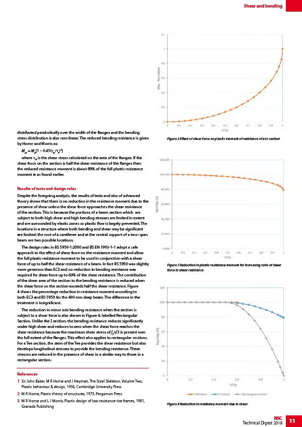
The design rules in BS 5950-1:2000 and BS EN 1993-1-1 adopt a safe
approach to the effect of shear force on the resistance moment and allow
the full plastic resistance moment to be used in conjunction with a shear
force of up to half the shear resistance of a beam. In fact BS 5950 was slightly
more generous than EC3 and no reduction in bending resistance was
required for shear force up to 60% of the shear resistance. The contribution
of the shear area of the section to the bending resistance is reduced when
the shear force on the section exceeds half the shear resistance. Figure
4 shows the percentage reduction in resistance moment according to
both EC3 and BS 5950 for the 400 mm deep beam. The difference in the
treatment is insignificant.
The reduction in minor axis bending resistance when the section is
subject to a shear force is also shown in Figure 4, labelled Rectangular
Section. Unlike the I section, the bending resistance reduces significantly
under high shear and reduces to zero when the shear force reaches the
shear resistance because the maximum shear stress of fy/√3 is present over
the full extent of the flanges. This effect also applies to rectangular sections.
For a Tee section, the stem of the Tee provides the shear resistance but also
develops longitudinal stresses to provide the bending resistance. These
stresses are reduced in the presence of shear in a similar way to those in a
rectangular section.
References
1 Sir John Baker, M R Horne and J Heyman, The Steel Skeleton, Volume Two,
Plastic behaviour & design, 1956, Cambridge University Press
2 M R Horne, Plastic theory of structures, 1979, Pergamon Press
3 M R Horne and L J Morris, Plastic design of low resistance rise frames, 1981,
Granada Publishing
Figure 2 Effect of shear force on plastic moment of resistance of an I section
Figure 3 Reduction in plastic resistance moment for increasing ratio of shear
force to shear resistance
Figure 4 Reduction in resistance moment due to shear