Projects and Features
Unique bridge at Milton Keynes

Elevation drawing of bridge
A new bridge at Whaddon Road, Milton Keynes is unique on two counts. It employs the design concept of continuing steel friction piles up out of the ground to form the bridge piers, and the piles themselves were pressed by a novel, vibration-free, quiet system.
THE bridge, in the Westcroft area, to the northwest of the city, was proposed by the town planners in the 1960s and 70s. It forms part of the final road link in the Milton Keynes City grid network.
Currently there are over 700 bridges in Milton Keynes. Concrete is the dominant construction material with a certain uniformity of aesthetic design that is almost synonymous with the highways network. Typically the local road underbridges will be single span with massive parallel wing-wall retaining walls. This number of bridges represents a significant initial investment and a significant maintenance liability.

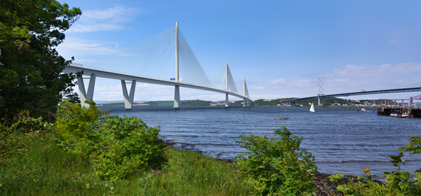
Fig. 1. The completed bridge
Pell Frischmann Consultants Ltd of Milton Keynes wanted to break this mould and developed a slender three span open bridge structure and presented it to the client English Partnerships (fig. 1). In common with most new bridges it was to be of integral construction (i.e. there are no expansion joints within the deck). What makes the design ‘unique’ is its construction simplicity, “a bridge on stilts.” The concept continued the bearing piles up out of the ground to the form the piers, without the need for pile-caps, and finally, by means of infill concrete for a minimum depth of two metres and reinforcement to the top, cast them directly into the bridge soffit forming a moment connection, without the need for bearings.
SITE GEOLOGY
Boreholes showed that the site geology consisted mainly of glacial clay derived from the Oxford Clay basal series. The clay was classified as stiff becoming very stiff and there were lenses of granular material within the clay. Pumping tests showed a high and fluctuating water table with some areas of artesian water pressure.
The design required a single structural member from foundation to soffit level. This combined with the water issues precluded the use of CFA and bored piles as water could enter the shafts and it would be difficult to provide the required surface finish to the exposed areas above ground.
Structures neither begin nor finish at ground level and the designer and client were keen to provide a sustainable form of construction which could return the site to its original conditions. Concrete piles are difficult to remove and the voids left behind have to be filled. Steel piles are extracted relatively easily leaving no lasting legacy.
STEEL PILES
Traditionally, Milton Keynes bridges were constructed well in advance of residential developments, but not so in the case of this structure. A large residential development was already in place within fifty metres of the bridge location. Noise and vibration were key issues and precluded the use of driven concrete or steel piles. For these reasons Pell Frischmann was keen to use steel. The next key issue was then how to install high capacity steel friction piles without the use of noisy percussive piling equipment.

Fig. 2. Pile pressing equipment
The answer was the quiet and vibration-less push-pull pile system developed by Dawson Construction Plant. This project was to be the first time the system had been used on a contract (fig. 2). The piles were formed from four Hoesch Larssen 43 sheet piles clutched together to form a 750mm square box. The push-pull system comprises four 200 tonne hydraulic cylinders which grip each of the four sheets in specially designed jaws. Once initially set up, partial driving takes place using the 6 tonne self weight of the cylinders and 40 tonne crowd force of the rig. The system then allows each of the sheet piles to be pushed down in sequence relying on the skin friction generated by the other three sheets and self weight of the equipment to provide the reaction to the 200 tonnes of pressing force. This system allowed the 16 box piles to be installed quickly and with minimal disturbance to the residents. If required, the piles can be removed by the same machine.

Fig. 3. Abutment piles
CONSTRUCTION
Following lengthy negotiations between English Partnerships, Pell Frischmann Consultants and the local housing developers, a contract for the highway and bridgeworks was let to Weldon Plant Ltd late in 2002. The specification of works required the use of the Dawson Construction Plant Ltd pressing system.
The central piles were pushed about 13m into the ground and the abutment piles around 8m with the use of a piling frame to ensure accuracy in setting out (fig. 3).
A maintained vertical load test and lateral load test were then carried out to the satisfaction of the engineer. Under vertical loading the abutment pile showed 3.5mm of settlement under a working load of 1,440 kN with the pier pile showing 4.7mm under a working load of 2,760 kN. The lateral load test confirmed the adequacy of the pile penetration for the predicted horizontal forces and movements.
COST AND TIME
Preliminary assessments show that there are very significant cost and time savings.
Simon Griffiths, Technical Director of Pell Frischmann and Robin Dawson, Managing Director of Dawson Construction Plant