50 & 20 Years Ago
The Humber Bridge
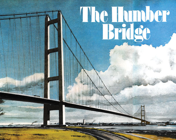
Of the Severn Bridge Sir Misha Black has said it is ‘the finest artefact of the present age and no work of any contemporary painter or sculptor was its equal.’ From the same practice now comes the Humber Bridge which bids fair to lay the claim of the earlier structure. In this article Dr Fisher of Freeman, Fox & Partners describes the bridge and outlines the reasons which led to the choice of the materials of construction.
After more than 100 years of campaigning for a bridge across the Humber estuary, construction of the bridge has begun. In four years’ time the bridge will be complete. It will be a suspension bridge with a main span of 1,410m – longer than any other clear span in the world. More important, it will join together the two sides of the Humber estuary which, hitherto, have developed separately. Without the bridge the region is cleaved into two by the estuary. With the bridge, growth will be generated in both economic and social activities in the new County of Humberside.
The bridge is sited between Hessle on the north bank and Barton-upon-Humber on the south bank, about 5 miles west of Kingston upon Hull, at a point where the estuary narrows. It will cut up to 40 miles of road journeys to and from centres in the Humberside region and relieve traffic congestion over the lowest crossing of the Humber, Boothferry Bridge at Goole. It will also replace the uncertain New Holland paddle-steamer.
The main span is 1,410m (4,625ft) and the side spans 280m and 530m on the north and south sides respectively. The bridge will carry dual two-lane carriageways able to cope with about 50,000 vehicles a day. Along each side of the deck there will be a pathway for pedestrians and cyclists. The bridge deck will give some 30m clearance above high water – sufficient for the shipping that goes farther upstream.
Almost from time immemorial there has been a demand for a fixed crossing over – or under – the Humber estuary, which has cut Hull off from the south and Grimsby from the north. and both from each other. More than 100 years ago plans were made for a railway crossing. Both bridge and tunnel schemes were proposed, but nothing ever came of them. Both road and rail plans were reconsidered during the late 1920s and a multi-span bridge was preferred to a tunnel on grounds of cost. Parliamentary plans were prepared and Government help promised with the offer of a 75% grant. However, the promised grant was withheld owing to the national financial crisis, and the Parliamentary Bill was withdrawn.
Still proposals continued to be made but they came to nought. Multi-span bridges were resisted by the shipping interests because of the possible interference the piers might have on movements of the deep-water shipping lane. Tunnels, whether for rail or road, were out on the grounds of cost. Then, inspired by the completion of the Golden Gate Bridge in San Francisco in 1936, at that time the longest-span bridge in the world, plans were prepared by Mr (later Sir) Ralph Freeman for a suspension bridge with a main span of 4,500ft – 300ft more than Golden Gate. The threat of war, however, stopped any progress being made.
After the war local interests revived the bridge proposal but restrictions on capital expenditure continued to prevent its fruition. In 1959, however, a major step was taken with the passing of the Humber Bridge Act. This Act, promoted by the Kingston upon Hull Corporation, brought into being the Humber Bridge Board, with the support of all the surrounding local authorities, and empowered the Board to construct and maintain a suspension bridge with a single span right across the river; to acquire the necessary lands; to take tolls and to borrow such sums as were required to build the bridge. Nevertheless, Government consent to raise the loan was still required.
Studies continued into the regional and traffic problems and, in 1969, the Central Unit for Environmental Planning published a report ‘Humberside – a feasibility study’ which recommended that, to avoid wasteful expenditure in duplicating facilities of both banks, the Humber Bridge should be completed by 1976. Traffic studies in 1969 predicted that, with the toll charge likely to maximize revenue, the number of vehicles using the bridge daily when it is first opened will be 20,000. On the basis of minimum expected growth in the region, this figure is expected to reach 34,000 by AD 2000 or a maximum of 58,000 vehicles a day if full planned expansion of the area is implemented.
Discussions took place between the Humber Bridge Board and the Department of the Environment about financing the project and, in May 1971, the Minister for Local Government and Development announced that he had agreed to the bridge going ahead, with work starting in 1972; the Government would lend the Board 75% of the cost, the whole cost to be repaid from tolls; and that he had authorized a number of road schemes in the region. Simultaneously, the Board confirmed that Freeman Fox & Partners of London (who had been involved in schemes for the crossing since 1928) would be the consulting engineers for the project.
The Humber Bridge will belong to the same “family” of modern suspension bridges as the Severn, completed in 1966, and the Bosporus Bridge in Istanbul, to be completed during the summer months this year. Like the Severn and Bosporus, the main deck girder of the Humber Bridge will be a continuous steel box girder of aerofoil crosssection which will provide the necessary stiffness to counter the effects of wind loading.
The nature of wind loading on a long-span bridge is of two kinds. First, the direct forces on the bridge due to its resistance to the wind. These forces can be estimated with reasonable accuracy once the maximum speed of the wind is known and the resistance characteristics of the bridge established. In addition, however, suspension bridges are susceptible to wind-induced oscillations, particularly of the deck, that cannot be analysed solely by calculation, but for which engineers have to resort to tests on models in wind tunnels to prove their designs. Any wind blowing across the bridge gives rise to vortex shedding that generates forces which tend to deflect the deck alternately upwards and downwards. If the frequency of vortex shedding approaches the natural frequency of the suspended structure, oscillation of the deck is induced. At the critical wind velocity when the two frequencies coincide a runaway condition can occur – as brought about the failure of the Tacoma Narrows Bridge in 1940. In that case, the natural frequency of the bridge both in flexure and torsion (bending and twisting) were close, so that Tacoma oscillated in flexure and torsion simultaneously. Several methods can be adopted to avoid such happenings. By appropriate choice of deck shape the exciting forces can be reduced; secondly, natural torsional and flexural frequencies of the bridge must be unequal; and, thirdly, adequate damping should be provided to dissipate energy.
An immense stride forward in tackling these problems was made in the design of the Severn suspension bridge. Prior to that the deck girder on long suspension bridges had been designed with deep, heavily cross-braced trusses below the deck to develop the appropriate torsional and flexural stiffness required to prevent combined twisting and bending oscillation under wind loading. In turn, these trusses had been better than the shallow ‘bluff’ plate girders used at Tacoma, producing less ‘exciting force’.
The Severn saw the deep truss girders replaced by a shallow aerofoil section that owed much of its conception to the wing of an aircraft. Not only did it offer a reduced ‘drag’ from wind loading but its streamlined form greatly reduced the exciting forces generated by the wind. It was also much stiffer in torsion for a given weight than the steel trusses, so reducing the deadweight of the deck and lessening the forces in the cables and on the towers and anchorages. The diminished drag on the suspended structure resulted in greatly reduced transverse forces on the towers. Thus the sizes of the cables, the towers and the foundations, and in consequence their costs, could be significantly reduced. As a bonus, maintenance costs were also cut, since painting the large surfaces of an aerofoil box is much easier than painting the many small faces of braced trusses.
Another innovation of the Severn Bridge concerned the hangers, or suspenders, by which the deck section is carried from the main cables. One effect of anti-symmetric oscillations of the deck is to cause local longitudinal displacements of the main cables relative to the deck as the latter rises and falls. Originally the hangers were vertical ropes that provided negligible resistance to such cable displacements. At Severn the hangers were ‘triangulated’, i.e. spread in a diagonal pattern, below the main cable. This arrangement restricts horizontal displacement of the cables and also takes advantage of the hysteresis or energy-absorbing property of the steel wire-rope hangers. An added resistance is thereby provided to oscillatory movements of the suspended deck. Both these innovations at Severn, which have been patented, are used on the suspension bridge over the Bosporus in Turkey, now nearing completion, and form part of the design of the Humber Bridge.
On the north side of the river the pier below the tower will be built at the high-water mark and the northern anchorage nearly 300m away on slightly higher ground between Hessle Golf Course and the Hull-to-Doncaster railway line. On this side of the river a hard, well-jointed bed of chalk comes close to the surface and is covered by a tough glacially deposited chalky boulder clay. The chalk bed will provide a good foundation for the anchorage – a massive concrete block, 65·5m long by 39m wide by 36m high, tied into the bedrock at a depth of 21m to resist a pull of 36,000 tonnes – and for the pier, a reinforced concrete slab, which will impose a downward thrust of 54,000 tonnes. Beyond the anchorage, the top layer of boulder clay will also provide a good basis for the approach embankment and the toll plaza.
On the south side, more difficult ground conditions will have to be overcome. The pier below the tower will be sited in shallow water 500m from the river bank and the southern anchorage will be 30m inshore of the water line. This area is a flat, low-lying area of soft alluvium underlain by boulder clay interleaved by laminations of sand and gravel. Below the boulder clay, 30m down, is a deep bed of very stiff, heavily fissured Kimmeridge clay and the foundations for both the pier and the anchorage will have to be taken down into this clay.
The Barton pier will be a cellular structure 42m long by 11m wide and 16m high carried on twin caissons each about 24m in diameter and sunk about 36m below the river bed into the clay. The Barton anchorage will be a similar block to that of the Hessle bank but will be supported on a cellular foundation, 72m long by some 40m wide, and filled with sand and water; it will reach 35m deep into the clay.
In the past, most major suspension bridges, particularly in the USA, have been built with steel towers. Humber, as well as having the longest-yet main span, will also be notable for the towers which will be of reinforced concrete, and built by ‘slip forming’. At Humber, the towers will each have two legs rising to a height of about 158m above the water and joined at four levels by cross beams, one just below the deck level, one at the top and two more in between. The legs will be tapered from 6m square at the base to 4·75 × 4·50m at the top, and will be hollow with a wall thickness at the base of 1.50m. One leg of each tower will contain a service lift from deck level to the top to enable maintenance men and their equipment to be carried up for work along the main cables.
Concrete has been chosen for two reasons: firstly, the towers are essentially compression members for which concrete is intrinsically the more economical material; secondly, developments in the concrete industry make this material very attractive. There is also an additional bonus: modern concrete weathers well and has an almost unlimited life without requiring further surface treatment so that maintenance costs on the towers should be small.
With the towers built to their full height, the body of the anchorages concreted, and the saddles for the cables in position on the tower tops and in the anchorages, the next stage will be the erection of the main cables. Each cable is made up of 37 strands and each strand consists of 404 galvanized high-strength steel wires of 5mm diameter; in addition, the Hessle side cable will also include four smaller strands each of 200 similar wires.
The method of erecting the cables for suspension bridges is known as ‘spinning’ and was originated 90 years ago by John Roebling in the USA. It was first used in the UK for the Forth Road Bridge and then for the Severn Bridge. As a preliminary to spinning the wires, cat-walks are first erected along the line of each cable from each anchorage to the tower tops and between the towers, the levels of the cat-walks being adjusted to the same sag as the cables. The two cat-walks are tied together by braced cross-walks to allow access between them, and they are also tied back with storm cables to reduce swinging in the wind. Above the cat-walks a separate ropeway system is installed to carry and guide the wires during erection.
It will be appreciated that cable spinning is an essential part of the project and great care has to be taken to see that the wires do not become kinked; also that they are accurately laid into position so that all the wires will contribute fully to the strength of the cables.
The wire is delivered to the site in coils that will be re-reeled and spliced at site. The end of the coil is fastened to the near anchorage and looped over a pulley on the ropeway. The pulley is pulled from one side of the bridge to the other paying out the wire behind it – the side of the loop already fixed to the anchorage being ‘dead’ (i.e. not moving), the other half of the loop being ‘live’ and moving forward as the pulley travels along the ropeway. When the pulley reaches the far side, the end of the loop is removed from the pulley and fixed to the strand-shoe at the anchorage. The wires are placed accurately into position in the cable by men spaced along the cat-walks. The process is repeated until all the wires for one strand have been spun. Each strand, which is made up in a similar way, has its own position in the cross-section of the finished cable and its own location in the tower saddles and at each anchorage. When the spinning for the cable is complete, the wires are compacted together and banded into the circular crosssection of the cable. Erection of the two main cables proceeds simultaneously.
The next job is to fit the 242 permanent cable bands that form the fixing points for the hangers that will carry the deck. Each cable band consists of a pair of semi-cylindrical steel castings machined on the inside to give a close fit on the cables. After the deck has been hung in position the cables are covered in red lead and wrapped with layers of soft galvanized iron wire to protect them against the weather.
The completed deck will consist of a single continuous all-welded steel girder of aerofoil cross-section stretching from tower to tower and a similar girder in each of the two side spans. Expansion joints will be provided in the deck at each tower and at the abutments to take up changes in length that will occur.
Each girder will be made up from box sections, 18·1 m long and of the full width of the deck, that will be assembled in a nearby yard from prefabricated steelwork. The boxes will be brought to the bridge by barge. The boxes will be raised into position by lifting gear running on top of the main cables and fixed on to the hangers. The first boxes to be put into position will be those at mid-span and the deck erection will progress in both directions towards the towers, adjacent boxes being temporarily bolted together. When nearly all the boxes are in position, and the correct alignment achieved, the boxes will be welded together.
Simultaneously with work on the main span, both the side spans will be erected working from the anchorages towards the towers. With the deck girders complete, the expansion joints will be installed and the crash barriers and railings fixed in position. Finally, the mastic asphalt wearing surface will be laid on the steel deck-plate of the boxes to form the carriageways.
Although the major part of the project will be the building of the bridge structure, an important number of electrical and mechanical services will also have to be provided. Lifts will have to be installed in each tower to carry maintenance men -and equipment to the top. Road lighting will have to be provided across the bridge and for the toll area. Navigation lights will have to be fitted to mark the shipping channel and warning lights to aircraft on top of the towers. A toll system, complete with recording and checking equipment involving a small computer, will be required. Traffic lights and traffic warning signs- ice, high winds, lane closed, etc. – will be installed and so will a closed-circuit television system to permit traffic surveillance. An emergency telephone system will be available for motorists in trouble on the bridge. To supply the power for these services, the national grid will have to be tapped and transformers and switchgear built into the electrical distribution system. All the services will be directed from a central control room in the administration block to be built on the north side, close to the toll plaza.
The Humberside Feasibility Study called for completion of the bridge by 1976 if full planned expansion of the region was to occur in the early 1980s. The start on construction sees the beginning of the culmination of 100 years of campaigning for a crossing of the Humber estuary and the foundation for the full development of the new County of Humberside.
Client: Humber Bridge Board
Consulting Engineers: Freeman Fox & Partners
Main Contractors
Sub-structure: John Howard and Co. Ltd
Superstructure: British Bridge Builders
From Building With Steel May 1973