Projects and Features
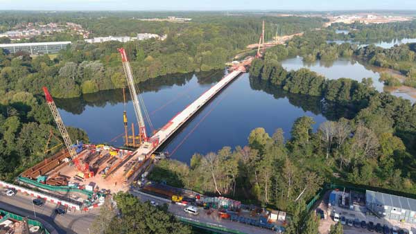
Swing bridge slides into place

Eight masts support the bridge’s cables
Symbolising regeneration, Media City’s steel swing bridge was constructed from modular sections, while the deck was launched into position via an innovative sliding procedure.
FACT FILE: Media City Footbridge, Salford
Architect: Wilkinson Eyre
Main contractor: Balfour Beatty Regional Civil Engineering
Structural engineer: Gifford
Steelwork contractor: Rowecord Engineering
Steel tonnage:410t
Spanning the Manchester Ship Canal, the £8.3M state of the art Media City Footbridge provides pedestrian access into the heart of Salford’s fast expanding Media City Development.Covering a large portion of former docks and quays, the development will soon be the home for several BBC departments, while a host of other media and production companies are expected to relocate there in the near future.
The bridge links the Media City site with South Quay, adjacent to the Imperial War Museum North. As well as enhancing access between the two sites, the bridge has also been designed to be a symbol of regeneration and a marker for further development.
The design of the Media City Footbridge is far from being run-of-the-mill as this asymmetric cable stayed structure’s main span pivots through 71 degrees to allow large vessels to pass along the canal. Choosing a swing bridge design over a fixed crossing was one of the main design issues, and the choice was made as there is a public right of navigation along the Canal. Although ships don’t enter the Port of Manchester as regularly as they once did, the bridge design had to accommodate any possible ship movements.

Artistic vision of completed bridge and development
Structurally the bridge comprises two spans; the main pivoting span crossing the Canal is 63m long, with a short back span of 18m. The back span was constructed as a hollow steel box and then filled with concrete to form the bridge’s counterweight for balancing the main span during opening.
The main span’s deck is fabricated as a shaped internally stiffened orthotropic steel box, with pedestrians walking on an epoxy aggregate applied coating. The deck box is a fully welded structure and sealed against the ingress of moisture, making the internal areas maintenance free.
The asymmetric form of the bridge’s deck span utilises a fanned array of eight, shaped CHS steel masts which converge at their bases atop a sculpted pedestal. The masts are up to 30m tall and support the bridge deck via high tensile steel cables anchored to the east side of the deck.
The deck is supported at 6m centres by the steel cables, which are anchored at their upper and lower ends using fork connectors onto steel outstand lugs aligned in the plane of the stays at the mast tip and deck connections.
“The most economical method of constructing this bridge was to fabricate as much of the structure off-site as possible,” explains Rowecord Engineering Contract Manager Gareth Summerhayes.
To achieve this steelwork contractor Rowecord fabricated the majority of the structure in modular sections, which were then brought to site to be welded together and assembled adjacent to the bridge’s final position.

Temporary works were installed while the bridges’ masts were all erected. These works had to remain in place until all the cables were attached
The main span, which has a width that fans out from 6m to 18m, was fabricated in three sections, while the shorter backspan was fabricated as one section. All steel sections had two coats of paint applied at the factory, and then a further two were applied once the welding had been completed.
Prior to the spans being assembled Rowecord first had to install the steelwork for the pivot bearing. The pivot for the bridge comprises a large steel casting welded into the pivot zone of the steelwork deck and mounted on a slewing bearing, which in turn is supported on a fabricated steel structure.
This arrangement provides vertical support; resists the overturning moment generated about the horizontal axes and also provides horizontal restraint during bridge rotation.
“We then slide both of the spans into position, with the main span first and then the backspan,” says Mr Summerhayes, (see box story). “Once these were in position we were then able to erect temporary works to allow the masts and cables to be erected and installed.”
With temporary works supporting the spans, as well as beam and column steel works supporting the masts, the cables were attached and correctly tensioned. Only when all of the cables were in position were the temporary works removed.
Summing up the project, Mr Summerhayes says: “This was a unique project from start to finish. Not only was the slide procedure and construction method slightly unusual, but the bridge’s design is also unique as the deck is curved in plan and elevation.”
Sliding a bridge into position

The slide procedure for the main span was carried out over 36 hours and involved jacking up the structure approximately 500mm off its temporary supports onto a skid track system that incorporated a pair of 40m-long ‘Kursk’ beams.
The steel beams are referred to as ‘Kursk’ beams as they were used as part of the recovery operation in 2001 to raise the Russian submarine of the same name.
“This procedure was used as it allowed us to fully assemble the bridge sections on the quayside without having to work over the water,” says Rowecord Contract Manager Gareth Summerhayes.
Finally the structure was jacked down onto its slew ring bearings where it will pivot using six hydraulically operated drive motors to rotate the bridge between its open and closed positions.
A similar procedure was then undertaken to move and position the smaller backspan of the bridge, which had been filled with counterweight concrete and consequently weighed more than 100t.