Technical
Stiffened moment connections
Alan J Rathbone, Chief Engineer for CSC, explains the practicality of applying welds to stiffeners while maintaining adequate strength.
Introduction
In the haunched moment connections of portal frame structures it is common practice to provide stiffeners to achieve the necessary moment of resistance in the connection. These stiffeners are welded to both the flange and web of the column (and in some cases to the web of the beam and the endplate). For some stiffeners the detailing of the welds on the column side can be problematic when trying to balance the practicality of applying the weld with the requirements for adequate strength.
Cap plate details
In design, cap plates can be used to advantage when there are significant reverse (negative) bending moments applied to the connection. In this case they can enhance the compression resistance of the column web both in bearing and buckling. Lifting devices can be incorporated into them to assist with ‘clean’ lifting of the column into its erected position.
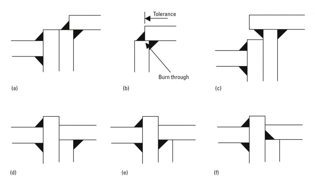
The ‘standard’ detail for a cap plate is shown in Figure 1(a). The end plate and column top are aligned and the cap plate is mounted on the top of the column. The simplest weld is single sided and follows the full profile of the column.
This may prove inadequate in design terms and so the double sided weld as actually depicted in Figure 1(a) may be adopted. As indicated in Figure 1(b), due to the variations in the rolled size of the column section and the length and positioning of the cap plate there may be a tolerance issue. For lighter columns with thin flanges there may be a possibility of burning through the corner.
Alternative details can be ‘invented’ such as those shown in Figure 1(c). This is not to be recommended since the raised column top and the oversailing stiffener may interfere with other components in the eaves area. Also, the cap plate may be too distant from the beam flange to be convincingly able to assist with the compression resistance of the column since the point of rotation of the connection is assumed to be about the centre line of the beam flange (in reverse bending).
The other alternatives shown in Figure 1 are variations of the same concept. That is, to ensure that the cap plate is in line with the beam flange and hence forms a direct load path. This relies on the cap plate and its welds being made flush after welding so that they could be considered as ‘fitted’. ‘Fitted’ infers that the cap plate resists the component of the compression from the beam flange in direct bearing and hence needs only nominal welds. The variations in Figure 1(e) and 1(f) require a ‘prep’ for the welding and so are less desirable. Before attempting to adopt any of the ‘fitted’ details, the steelwork contractor should be consulted to ensure that such a detail can be achieved with normal workshop practices.
The ‘standard’ detail with single or double sided welds is simple to execute and is the first choice for most steelwork contractors. In the design of these welds, whether single or double sided, any opening of the weld, due to flexure in the column flange under positive bending, is not normally taken into account. Fortunately, the forces required of the stiffener and its welds under this loading condition are relatively small. For significant reverse (negative) bending moments, the cap plate and its welds are likely to be subject to a significant compression force (in the same way as a normal compression stiffener at the bottom of the connection). This may create more difficulty in satisfying the design requirements and the ‘fitted’ cap plate may then be worthy of consideration.
Of course, if the reverse (negative) bending moments are relatively small then the unstiffened column web, even allowing for the end condition, is likely to be adequate. A cap plate is then not required from a design point of view and, given that it is not required for other purposes, should be omitted to improve cost effectiveness.
Full depth stiffeners – web welds
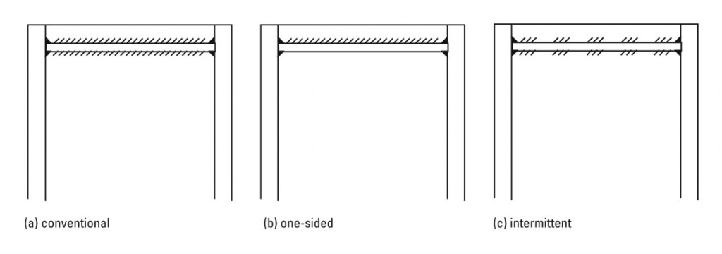
As an alternative to a cap plate, a pair of full depth stiffeners can be used that are positioned just below the column top as shown in Figure 2(a). This is a much more robust detail in design terms as the flange welds are symmetrically disposed around the stiffener. The position of the stiffeners will be such that they align with the beam flange and thus can be clearly taken to be fitted and hence require only nominal welds.
However, it is not often used in preference to a cap plate because there are two piece parts and significantly more welding is required. Incorporating lifting devices is usually impractical.
The cost component in fabrication of having to use full length welds along the whole stiffener to column web interface could be reduced by adopting one of the two details given in Figure 2(b) and (c). The one sided weld of Figure 2(b) could distort the plate during the welding process but is probably more efficient to lay than the stop-start of the double sided stitch weld in Figure 2(c). A further alternative (not shown) would be to provide a longer stitch alternately on each side of the stiffener. There would be less stop-starts and the alternating sides would maintain the line of the stiffener.
In design terms given the same amount of weld material, the continuous one sided weld is also more efficient since for the stitch weld at each start and stop, a leg length must be discounted in the design length of the weld. The stitch weld should comply with the minimum length requirements of BS 5950-1: 2000.
In the normal double sided weld detail, the length of weld, being the full width of the web, is usually more than adequate to resist the design force and the use of a relatively small weld (6 mm fw) is usually found to be an over-provision. The alternative details with less total length of weld are likely therefore still to be adequate.
Whilst the details in Figures 2(b) and (c) are suggested as alternatives to a cap plate, such savings in weld material could also be used for full depth stiffeners used in standard situations – eg – as a compression stiffener at the bottom of the connection.
Of course, for both positive and negative bending moments, the column web in compression may be adequate without stiffening. In this case full depth stiffeners should be omitted to improve cost effectiveness. Indeed, particularly in multi-storey construction, increasing the column size (web thickness) to avoid stiffening can be a cost effective solution.
Diagonal stiffeners – flange welds
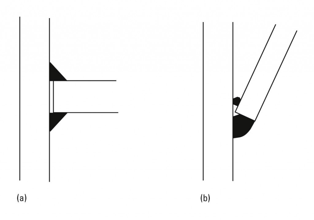
The standard flange weld details for compression and diagonal stiffeners are shown in Figure 3(a) and (b). These are taken from the Green Book on moment connections for which adequate design rules are provided.
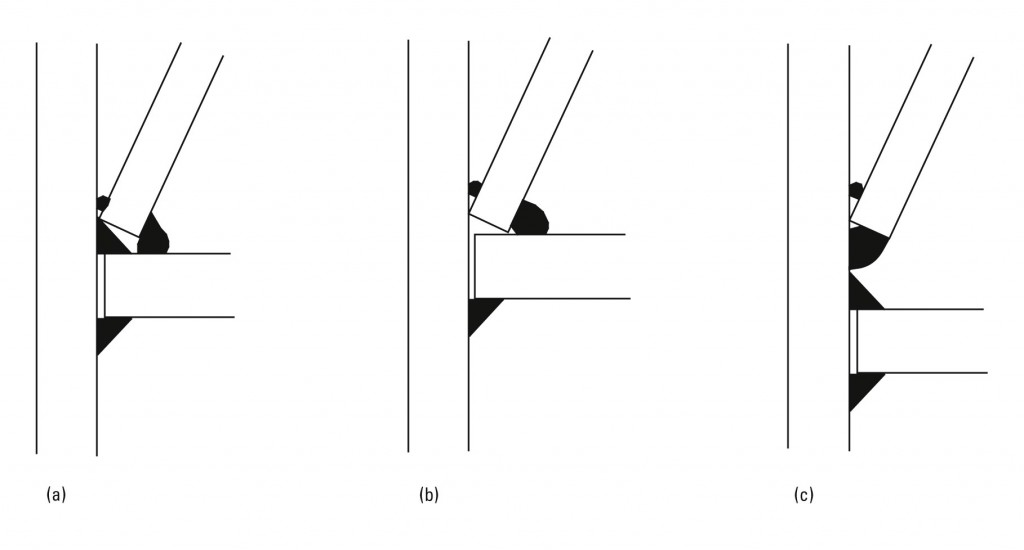
However, compression and diagonal stiffeners are often used together and this creates a more difficult detail for the flange weld and consequently a difficulty in satisfying the design requirements. Three alternatives are shown in Figure 4(a), (b) and (c). The main difficulty in the weld detail stems from the steepness of the diagonal stiffener compounded by the crowded nature of the joining elements.
In all cases (including the single stiffener detail of Figure 3(b)) the diagonal stiffener is usually sufficiently angled that the weld on the top side of the stiffener can only be placed as a sealing run and this cannot be relied upon in design. Indeed, the diagonal stiffener may be sufficiently steep that a sealing run cannot be placed from the top and so should be placed from underneath (this is not possible with the detail in Figure 4(a) since the compression stiffener is placed first).
Figure 4(c) overcomes the crowding issue by separating the two stiffeners such that the single stiffener details of Figure 3(a) and (b) can both be used. Clearly they should be separated sufficiently to allow the weld material to be placed without difficulty. As shown the shear stiffener weld might still be difficult to place and moving the two stiffeners further apart would interrupt the load path from one to the other.
The details in Figure 4(a) and 4(b) are probably the most common in practice. In Figure 4(b), if the compression stiffener is ‘fitted’ then the flange weld need only hold it in place (and resist any (smaller) tension forces in reverse bending). However, the diagonal stiffener is only held by a single fillet weld. Again this may be adequate since most of the shear transfer from the web panel to the shear stiffener occurs through the web weld. The problem with this detail occurs when the compression stiffener is not fitted and in all cases when the diagonal stiffener to flange welds must resist a significant design force. When the compression stiffener is not ‘fitted’ then the use of the detail in Figure 4(a) would overcome this – the compression stiffener being placed first. Improvement in the robustness of the weld can be made by ‘preparing’ the end of the diagonal stiffener – effectively giving a full strength butt weld – but with the penalty of increased fabrication time and hence cost.
Of course, the preferred detail is to avoid the use of diagonal stiffeners altogether. In portal frame haunches this can be achieved by increasing the haunch depth (so reducing the shear) or increasing the section size or grade. In multi-storey construction other beams that frame into the web prevent the use of diagonal stiffeners. In this case the best option is usually to increase the column size or, if there is no other option, to use web plates – the standard detail for these requires a significant amount of welding.
The best advice in all of these situations is to consult the steelwork contractor – who knows what is achievable in the workshop and what is economic. It is the old axiom that least weight in the member sizes may pay the penalty of increased fabrication costs.


