Projects and Features
Spanning river and rail
Crossing numerous electrified railway lines and the River Clyde respectively, the last two steel bridges for Glasgow’s M74 project have now been erected. NSC reports.
FACT FILE: Auchenshuggle Bridge and Rutherglen Station Bridge, M74 Completion project, Glasgow
Main Client: Transport Scotland, Glasgow City Council, South Lanarkshire Council, Renfrewshire Council
Main Contractor: Interlink M74 JV, comprising Balfour Beatty, Morgan Est, Morrison Construction, Sir Robert McAlpine
Structural engineer: Jacobs/Atkins JV
Steelwork contractor: Cleveland Bridge
Overall project value: £445M
Steel tonnage: 3,796t
Glasgow’s M74 Completion project will provide the Scottish city with an urban motorway ring road as well as a major economic boost. Programmed to open in June, the new six lane motorway covers a distance of 5 miles and will complete a loop by linking the existing M74 to the M8 at a point just west of the Kingston Bridge.
One of the main challenges associated with the project is the route through busy southern Glasgow. A number of businesses and factories have had to be relocated because of the works, while the motorway has to cross a number of major roads, railway lines and the River Clyde. This accounts for the number of bridges – 14 in total, underpasses and deep embankments which have had to be completed.
Four of the project’s major bridges are steel structures, the M8 Eastbound Link Bridge (see NSC Nov/Dec 2009), the Port Eglinton Viaduct (see NSC February 2010), Rutherglen Station Bridge and the Auchenshuggle Bridge. The latter two structures were the final two steel elements of the project to be completed and both have now been erected.
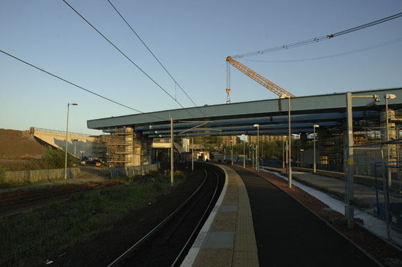
The 1,956t, 186m-long Rutherglen Station Bridge spans a multitude of electrified railway lines and this meant detailed consultation and coordination was required with Network Rail. All steelwork had to be assembled in a nearby yard and then erected during 2.5 hour rail possessions that took place during 16 consecutive nights.
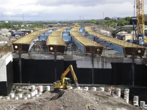
This bridge is formed from trapezoidal open top steel box girders which are curved in plan and elevation plus rotated transversely to form the bridge cross fall. The structure has four spans and was constructed with four lines of girders.
When it came to designing this bridge it quickly became apparent that the required girders, with widths across their top flanges of 5.5m, were going to be too wide to transport to site.
Although special transport orders may have been possible to transport these girders on part of their journey from steelwork contractor Cleveland Bridge’s Darlington facility to Glasgow, they were just too big to fit through city streets.
It was decided that the girders would be fabricated as a whole box but split down the longitudinal centreline so that they could be transported as half boxes at under 3.5m, which would require minimal transport restrictions.
The designers then developed a part penetration weld, much smaller than a full butt weld to enable the two halves to be quickly welded together on site.
“Building the girders as half boxes in the factory was a much quicker and easier solution rather than building the girders from flat panels on site – it allowed greater control and accuracy in achieving the geometrical tolerances,” says Stephen Osborne,Cleveland Bridge Project Manager. “When it came to assembly we’d also gained experience from doing a similar procedure with the much longer Port Eglinton Viaduct.”
In total there were 54 half girder deliveries which were then site welded to form 27 full girders ranging in length from 16m to 33m.
The boxes were then assembled into longer lengths, typically consisting of two whole boxes, to create 16 lifts varying in lengths and weighing between 70t and 190t.
A heavy lift Gottwald AK-680-3 mobile crane, with a 107m long boom and 600t of superlift counterweight was used for these lifts at Rutherglen Station. Self Propelled Modular Transporters (SPMTs) were also used to transport the girders from the site assembly area to the crane pick up position.
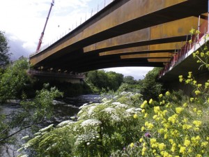
For the 1,840t Auchenshuggle structure, Cleveland Bridge fabricated and transported the steelwork to site as full box girders in 35 loads, with a maximum transport length of 27m, width of 4m and a weight of 85t.
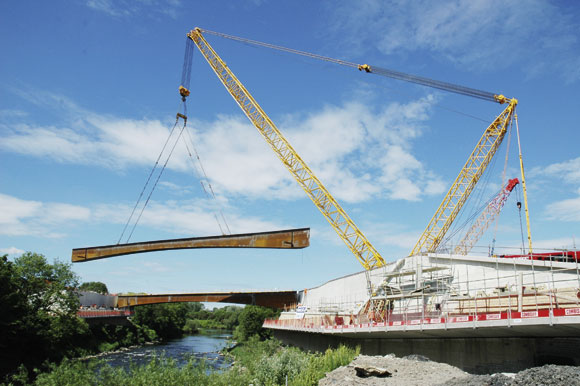
Once the steelwork was on site it was assembled into seven 90m-long girders weighing up to 300t each. Because this bridge spans the Clyde it was necessary to erect it in the full 90m-long spans, to avoid – for economic, environmental and safety reasons – working in the river with intermediate propping.
“This bridge was challenging as we were dealing with much larger girders and cranes,” says Mr Osborne. “The assembly took place on the bridge’s approach road and took us approximately 10 weeks to complete. There were eight welded and 20 bolted splices to join the girders together requiring up to 1,250 bolts in each.”
The girders were all erected over a seven day period, with one 300t girder being lifted into place each day. To cope with such loads this lifting procedure needed one of Europe’s largest strut jib cranes, the Demag PC9600 which has a huge 2,000t capacity.
The crane was imported from its previous job in The Netherlands and delivered to crane operator Sarens UK depot in Middlesbrough. It was then transported to the Glasgow site in 100 truckloads and then took nine days to assemble.
Each assembled girder had to be transported from the assembly yard to the crane pick-up point – using Self Propelled Modular Transporters (SPMTs) – a distance of nearly 50m.
Once in position beside the crane, each of the bridge’s seven girders was then lifted into position landing on temporary works on the two abutment shelves. The crane’s biggest lift was 314t at a 72m radius which required 900t of superlift counterweight.
As each lift was slightly different, the crane had to be disconnected at the end of each day and then its superlift reconfigured ready for the following day’s lift. This was a long procedure and took up to eight hours each time.
Once all of the girders were in position, secondary bracing was installed at abutment diaphragm locations. The bridge structure was then aligned, levelled and the bearings grouted into position. Once the bearing grout had cured the bridge was jacked onto the permanent bearings and the temporary supports and restraints removed, completing the erection.


