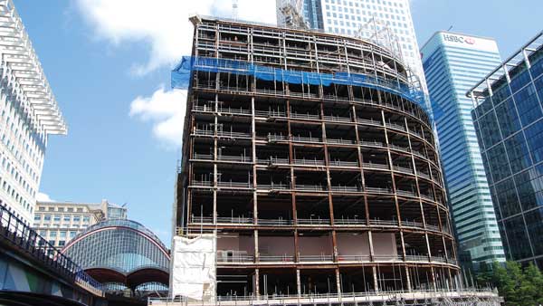
Projects and Features
Search & Rescue is framed for success

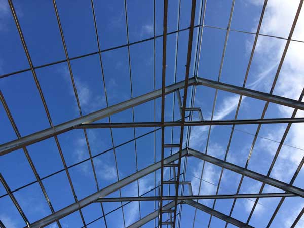
A spacious portal frame hall, featuring a wave pool and a mock helicopter suspended from a crane, serves as the focal point of a new steel-framed Search and Rescue Training Centre in Hampshire.
FACT FILE
Search and Rescue Training Centre, Lee-on-Solent
Main client: Bristow
Architect: Stride Treglown
Main contractor: Mildren Construction
Steelwork contractor: Snashall Steel Fabrications
Steel tonnage: 340t
A world-class Search and Rescue (SAR) Training Centre is currently being built in Lee-on-Solent, Hampshire. Once completed, it will offer a safe environment for enhanced crew training.
Located at Daedalus Airport, a former Royal Navy establishment, the new centre will include a simulation hall with a training pool and helicopter rescue hoist, teaching classrooms, brief/debrief rooms and medical training areas, as well as breakout and ancillary spaces.
Owned by Bristow, the company that operates search and rescue helicopters on behalf of HM Government’s Coastguard, the SAR Training Centre is located on a 1.55-hectare site at the airport’s Faraday Business Park.
Matt Rhodes, Director Business Development, Government Services for Bristow says: “This state-of-the-art training centre under development for Bristow Group will set a new benchmark in realistic and immersive training for search and rescue (SAR) crews.

“By simulating an aircraft ‘hovering’ over a pool at heights of up to 20 meters, it will test lifesaving teams in the most demanding rescue scenarios.
“It also reduces the need for training flights with real helicopters, increasing their availability for actual emergencies and reducing environmental impact.”
Following an archaeological dig, work on the project began during the autumn of 2024, with the excavation of the training pool and the installation of its piled foundations. The concrete-formed pool, which measures 30m-long × 17m-wide and 4m-deep, will hold 1.7 million litres of water and be integral to the centre’s training activities.
Housed inside a 23m-high portal-framed structure known as the rescue hoist trainer (HRT), the pool area will be a sealed box, with no windows to the outside world, allowing for nighttime simulated training.

Rescues at sea will be replicated with a mock helicopter hung from an overhead crane’s hoist, while fans, located in the pool’s concrete structure will recreate sea conditions. There will also be a climbing wall to provide simulation of cliff-face rescue operations.
Once the pool had been formed, the steelwork for the surrounding portal structure could begin. Founded on pad foundations and creating the elevations of the hall, are a series of 838 × 292 × 176 universal columns, spaced at 7.5m centres.
“The column sections are bigger than would ordinarily be used for a frame of this size,” says Mildren Construction Project Manager Marten Platt. “This is because they are supporting two high level crane beams that run the length of the hall, as well as an overhead crane and helicopter, all of which has a combined weight of 50 tonnes.”
The columns are working hard, because as well as supporting equipment and being stiff enough for the subsequent vibration, they also support a series of 27m-long roof rafters. These were fabricated and delivered to site in two pieces by steelwork contractor Snashall Steel Fabrications (SSF). Once onsite, they were assembled into one section and lifted into place using a 70t-capacity mobile crane.

Because the chlorine in the training pool water will create a corrosive environment, all the portal frame’s steelwork has been galvanized.
This requirement had a bearing on the steel design, as the 23m-tall columns would have been too long for a UK hot-dip galvanizing tank. “They have a spliced design, and similar to the rafters, the columns had to be fabricated, galvanized and delivered to site in two pieces, before being erected as one large section,” explains SSF Project Director Mike Austin.
As the RHT is at the heart of the scheme’s training operations, the portal frame was the initial part of the steel erection programme. Once it was up and the cladding installed, the surrounding steel elements could be erected.
Three of the RHT’s elevations (east, north and west) are abutted by either two or single-storey steel-framed structures. The south elevation will be left clear, as this end of the RHT accommodates the entrance. Large double doors will allow equipment to be taken in or out.

Arranged along the north and east elevations of the RHT, the centre’s teaching, medical and meeting room spaces are accommodated within two-storey areas.
Allowing trainees to view the simulated rescue operations from their classrooms, the upper floor along the northern elevation will have two large windows overlooking the training pool (the only windows in the RHT).
For the most part, these areas are 8m-wide, column-free spaces with a concrete ground floor slab and an upper level formed with steel beams supporting precast flooring planks.
SSF left some roof members out to facilitate the installation of the precast planks once the steelwork was complete. The gaps were large enough for the planks to be craned into place The missing steel members were then installed once the flooring had been completed.
Adjoining the two-storey element, the main entrance to the training centre is located along the north-east corner within a single-storey element.
Completing the training centre’s steel frame, positioned along the western elevation of the RHT there is an 8m-wide single-storey building that will house the facility’s plant.
The SAR Training Centre is due to be complete by the end of the year.

Flooring solution
The search and rescue training centre in Lee-on-Solent is a good example of a project using steel beams to support precast flooring planks. Liam Dougherty of the SCI offers some guidance on open section steel beams, supporting precast flooring planks in the temporary condition.
A system of precast flooring planks can provide lateral restraint to an I-profile’s top flange once the joints between the planks are grouted and/or a screed is cast. However, prior to grouting, such resistance will be lost, due to the lack of longitudinal shear transfer between the individual precast units. Without a shear connection, the planks can translate longitudinally relative to one another. Lateral stability is therefore reliant on the restoring moment that develops, if the beam starts to buckle. Provided the precast units are of equal span either side of the beam, they may be assumed to provide adequate restraint for spans of up to 8m. Information on the background to this limiting span can be found in AD 511.
In the temporary condition, when only one side of steel beam is loaded with precast planks, such that the loads do not act through the shear centre, the beam may twist due to the out of balance moment. Open sections such as I-profiles are relatively flexible in torsion and twist introduces longitudinal stresses which reduces the bending resistance.
At any point in the span of a member, the torsion is carried partly as St. Venant torsion and partly as warping torsion. As a simplification for I-profiles, clause 6.2.7 (7) of BS EN 1993-1-1:2005 allows the effects of St. Venant torsion to be neglected.
Guidance on the behaviour of beams in torsion and the design of open sections in torsion in accordance with Eurocode can be found is SCI P385 ‘Design of Steel Beams in Torsion’.
SCI P385, indicates a maximum twist of 2° is a practical limit for the serviceability criteria. In many instances, for I-profiles the serviceability limit on twist will govern the design. In trying to understand the basis of the two degrees’ limit, Wates Construction in collaboration with SCI undertook testing on I-profiles to examine the torsional behaviour of beams when using standard fabricated end connections and current precast plank installation methods. In future technical articles, details of the tests undertaken will be explained, test and theoretical results will be presented and an analysis of the results given.