Projects and Features
Removal of temporary lifting attachments on bridges
Certain topics can trip up an engineer more often than others, and without doubt, fatigue is one. In this article, the SCI’s Max Cooper discusses temporary lifting attachments used to install steel bridges, outlining the fatigue risks and the specific requirements for designers and fabricators.
When a structure is subject to cyclical loading, it is susceptible to fatigue. Fatigue is a phenomenon where small flaws may open up under repeated load cycles to eventually form cracks, and may result in failure despite each one of the load cycles resulting in a stress level far lower than the steel’s design strength. In structural steelwork this may occur in members irrespective of whether they are in compression or tension due to the effect of high tensile residual stresses which arise from the fabrication process.
Designing for fatigue can be a source of headaches to both designers and fabricators. Factors that are often immaterial to the design of non-fatigue-susceptible structures – such as stress concentrations, stress ranges, and weld detailing – are often critical to the reliable performance of the fatigue-susceptible structure. As such, if you are designing, detailing, or fabricating a fatigue-susceptible structure, alarm bells should be ringing that there are a whole host of different requirements that you need to meet, and that seemingly small details can have an outsized impact on the fatigue performance of a much larger structural element.
One such ‘minor’ detail is a temporary lifting attachment point on bridge structures, which leads us to the subject of today’s article: do they need to be removed?
A common request
On more than one occasion, the SCI’s Advisory Desk has received correspondence from designers of composite bridge projects regarding fabricators proposing to cut down temporary lifting lugs to a short stub and grinding the top smooth, rather than completely removing the attachment and grinding flush with the parent flange. This practice is noted in Section 6.2 of the BCSA Guide for the Erection of Steel Bridges though it is important to highlight the passages “…in consultation with the Designer…” and “…using approved cutting methods” which should alert the fabricator that under no circumstances is this a decision that they should be taking alone.
Whilst complete removal will always be the preferred solution from a design point of view, achieving this on site is often a time-consuming and complex process for the contractor. In order to balance the needs of all project parties, a more holistic approach is to assess each lifting lug location and establish whether it can be left in the permanent works, needs partial removal or needs complete removal. The preferred solution should be established on a case-by-case basis, requiring dialogue between the designer and contractor.
Left in place
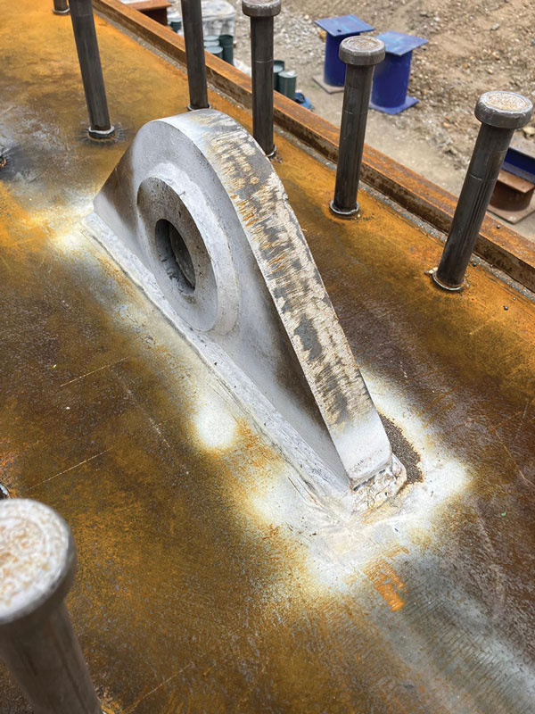
If a lifting lug is to be left-in-place in the permanent works without modification, this should only be permitted following acceptability of the following checks:
1) Obstructions to deck structural components
A left-in-place lifting lug will often cause obstructions to structural components needed for the deck construction, such as rebar and temporary works items. The detail should only be left-in-place provided all project parties are satisfied that there are no adverse implications with respect to obstructions.
2) Stress concentration on the top flange
A welded lifting attachment introduces a new stress concentration. It typically downgrades the fatigue Detail Category on its supporting flange to 56 (refer to BS EN 1993-1-9 Table 8.4). Unless expert fracture mechanics studies justify a higher category, the flange must be reassessed by a competent person (invariably the permanent works designer) for this significant reduction in fatigue performance. The fatigue Detail Category can also be improved by sensible detailing of the proposed lifting lug location. The designer should ensure that no part of the lug or its welds is closer than 25mm to a flange edge and that there are no lugs proposed in regions of high fatigue loading.
3) Brittle fracture and lamellar tearing implications on top flange
The attachment must be assessed by a competent person for brittle fracture implications, specifically calculating the increase in TRD from the National Annex to BS EN 1993-1-10. As a worst case a plate subgrade with a higher Charpy classification can be needed if the lifting lug is placed in an area under high tension stresses in the permanent works. Additionally, if the attachment welds are large, the risk of lamellar tearing through the top flange will be increased. Lamellar tearing must be assessed by a competent person using PD 6695-1-10 Clause 3.3. As a worst case, Z35 quality plate may be needed locally in the top flange in the lifting lug location if the lifting lug creates a cruciform joint with a tz value (as defined in PD 6695-1-10) greater than 25mm. It is considered good practice to scan the top flange plate for laminations before and after welding of the lifting attachment, in accordance with clause 5.3.4 of BS EN 1090-2.
4) Additional permanent works stresses at attachment location
A left-in-place lifting lug must be assessed to ensure that its shear stiffness within the deck does not cause cracking fatigue in its welds under fluctuating longitudinal shear loads over time. Within a composite steel girder, a left-in welded lifting attachment acts as a highly rigid shear connector providing additional shear connection to the concrete slab. This attracts additional longitudinal shear force that must be transmitted through shear stresses in the lifting attachment welds. If these longitudinal shear forces are excessive and fluctuating under traffic loads over time, there is a risk of fatigue cracking developing in the lifting lug welds, subsequently propagating into the top flange parent plate over time if left unchecked. The difficulty for the designer is that there is no codified approach to simply check the longitudinal shear force fatigue stresses picked up by a typical lifting lug detail cast into a concrete slab.
Engineering judgement, based on the susceptibility to significant longitudinal shear forces at the lifting lug’s location within the overall structure, in conjunction with complex analysis of the flexibilities of the lifting lug in conjunction with the surrounding shear studs under longitudinal shear fatigue forces are usually necessary for the designer to assess this risk in the absence of codified guidelines.
5) Fabrication and inspection quality
There is often a temptation for temporary works lifting attachments to be fabricated to a lesser quality, but this is unacceptable if they are to be left in the permanent works. It is essential that the fatigue capacities of the lifting lug welds and surrounding area are fabricated to the strength quality assumed by the designer. This is achieved by ensuring that the lifting lug plates and welds are fabricated to the same Execution Class and Quantified Service Categories (QSC) specified for the permanent works. Any more onerous QSC rating required as part of the assessment of the left-in place lifting lug must be clearly communicated by the designer to the fabricator for inclusion in the works.
6) Inspectability
The left-in-place lifting lug welds will usually not be able to be routinely inspected, being obscured by the concrete deck slab. It is recommended that the opinion of the future bridge owner is sought to establish whether they are satisfied with the potential maintenance liabilities of welded attachments that cannot be routinely inspected. The need for engineering judgement in this issue is commonplace considering the likely fatigue stresses at each lifting lug location balanced against the risks of other non-inspectable top flange welds such as shear studs and doubler plates. Either complete removal or adoption of a safe-life fatigue design philosophy for the non-inspectable welds are common client requirements in this regard.
It is the experience of the Steel Bridge Group that, whilst technically viable in certain situations, it is rare for all the above requirements to be met, thereby allowing a full-height lifting lug to be left-in-place in a bridge permanent works. Partial or complete removal is required in the vast majority of typical situations.
Partial removal
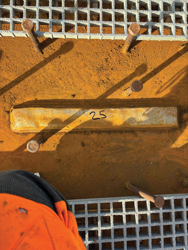
Partial removal involves cutting and grinding back the lifting lug to a nominal 25mm height above the permanent member surface.
Whilst the removal of the attachment to a small stub will typically prevent clashes with the deck rebar (discussed in item 1 above), the stub will still form a stress raising detail in a bridge structure, which needs fatigue and fracture assessment by competent persons. Where the remaining stub is shorter than the thickness of the lug, the Detail Category should be taken from BS EN 1993-1-9 Table 8.5, which varies from 56 to 36. The detail will also continue to pick up longitudinal shear forces in service. Quantifying these longitudinal shear forces is a complex task and will require the designer to consider the shear flow along the beam and the relative stiffnesses of the concrete flange, shear studs and lug stub. Items 2, 3, 4, 5 and 6 above will need to be satisfied before being able to justify leaving the remaining stub in the permanent works.
As a stub is to be left in the permanent structure, fabricators are reminded that the resultant cut edge needs to comply with all relevant Specification requirements required for permanent works steelwork. Care is needed with the stub removal works on site as inappropriate use of flame cutting or grinding back to the flange can alter the metallurgy of the steel or introduce new stress raisers. Procedures for cutting and grinding should be controlled on-site to ensure compliant hardness values are maintained on the cut edge and that the parent material is not gouged or otherwise compromised.
Complete removal
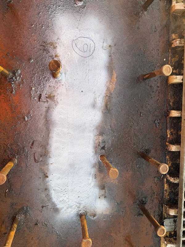
If a partially removed lifting lug cannot be justified in the permanent works for any reason, the lug will need complete removal to justify ignoring it in the permanent works fatigue and fracture assessment. Whilst often practically difficult due to the restricted access of adjacent shear connectors, best practice is for the lug to be initially cut leaving a stub at least 3mm above the permanent member surface and for the remaining stub ground smooth using an Approved Procedure involving grinding parallel to the member axis. Any accidental damage incurred during removal needs to be appropriately repaired and the final ground surface must be checked for freedom from cracking using magnetic particle testing.
Summary
While temporary lifting attachments may seem a minor detail, they can produce a significant effect on the fatigue performance of a bridge. Any deviation from complete removal and subsequent grinding flush of the parent beam flange requires the explicit approval of the permanent works designer, supported by appropriate fatigue calculations, and fabrication and testing requirements matching those of the permanent works. In order to do this, the steelwork fabricator must provide the permanent works designer with the detail, location and proposed removal methodology for each of the lifting lugs.
Contact: m.cooper@steel-sci.com