Projects and Features
Powering ahead with steel
Steel portal frames are the solution for three turbine halls for one of the UK’s latest power stations. Martin Cooper reports on the construction of EDF Energy’s new West Burton facility.
FACT FILE: West Burton Power Station, Retford, Nottinghamshire
Architect: EDF CIT
Main civil contractor: Kier Construction
Structural engineer: EDF CIT
Steelwork contractor: Fisher Engineering
Steel tonnage: 6,000t
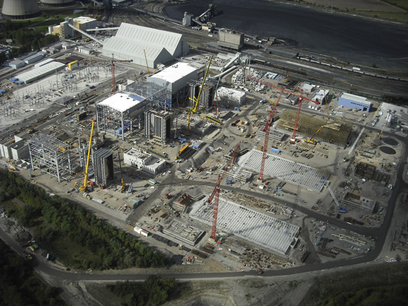
In order to meet future energy requirements EDF Energy is building a new 1,300MW Combined Cycle Gas Turbine (CCGT) power station at its West Burton site, near Retford, Nottinghamshire.
The new facility, which will be ready for commercial operation in 2011 and will supply enough energy for approximately 1.5 million homes, is being built adjacent to an existing 2,000MW coal fired power station, which means the site has much of the necessary infrastructure – such as access roads – already in place.
EDF Energy says the power station is being built using advanced, yet proven technology to provide an efficient and flexible plant to meet future energy supply requirements and to help its climate commitment to reduce the intensity of CO2 emissions from electricity production by 2020.
CCGT power generation is said to be the most energy efficient and clean method of fossil fuel generation. It involves burning natural gas, which turns a gas turbine with the waste heat used to turn a steam turbine. To supply the power station a new 19km long underground gas pipeline will connect it with the National Transmission System in Lincolnshire.
The connection to the electricity transmission system will be via a new 1km long underground cable to the National Grid substation which already exists within the West Burton site boundary.
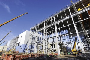
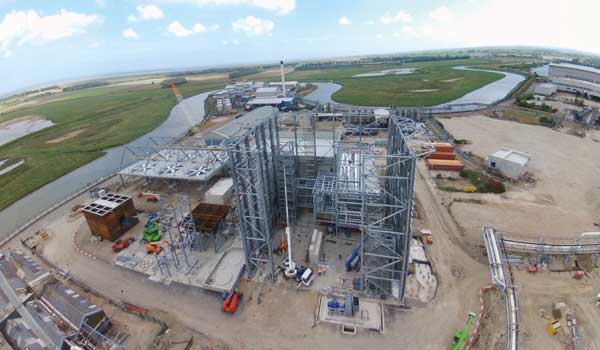
Work commenced on site in January 2008, with the main steelwork programme kicking off during the middle of last year. Many of the larger new structures on the site are steel-framed buildings, and this includes the three turbine halls.
The turbine halls are huge and each one of these identical portal frames is 32m high to the eaves, and measures 82m long × 35m wide. Below ground the steel-framed halls are founded on CFA piles which were installed after the former pulverised fuel ash (PFA) depot site was excavated.
In order to keep truck movements to a minimum on surrounding roads, none of the PFA was moved offsite, as all of the material has been relocated to another part of the huge West Burton facility.
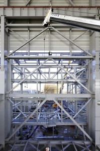
In order to give the turbine halls the necessary column free interiors a series of 4.5m deep × 35m wide trusses span the halls.
As the trusses are too long to lift or transport as one piece, they were brought to site in three equal sections. Two of these were bolted together on site, then this piece along with the remaining third section were lifted into place in a tandem lift involving two mobile cranes.
“Once they were in position the trusses were bolted together while being held up by the two cranes,” explains Fisher Engineering Site Manager Pat McLaughlin. “However, we needed three cranes to erect the initial bay for each of the halls, as we needed two trusses up and braced for stability.”
Supporting the roof trusses are a series of substantial fabricated plate girder columns spaced at 12.5m and 15m intervals. Brought to site in two 32m lengths these columns measure 1800mm x 600mm at the base, and were assembled on the deck before being erected as one 33t piece. Because the columns support an internal high level crane, the upper sections are smaller (weighing 9t instead of 24t) and have an L-shaped indent to accept the crane’s track.
Fisher Engineering has erected the three structurally independent turbine halls sequentially as they are positioned adjacent to each other in a row. Once each of the frames is up, the concrete slabs are poured, and plinths and pedestals for the turbines and associated equipment are installed.
“One of our main challenges is working around the numerous other trades on this busy site,” says Fisher Engineering Project Manager Barry Craig. “We’ve had to leave some large openings in the frames so equipment can be installed.”
Each of the turbine halls has two internal floors which are installed once the main concreting programme is completed. Fisher will eventually install 12,000m² of open mesh flooring for the entire project.
“Some of the flooring has had to be left out while the turbine hall’s equipment is installed. We then erect the missing sections of flooring once the internal installation has been completed,” adds Mr Craig.
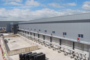
Sequencing of the overall works also has to take into account the turbine hall’s height. Consequently the cladding (which will eventually add up to 40,000m² on the halls) can not begin until the floors have been completed, as they add the necessary stiffness and bracing to the structures.
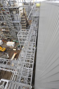
Running parallel to each of the turbine halls is a pipe rack which connects each hall to its own substation. Each rack is identical and has multiple levels of steelwork for its associated pipework. Fisher will ultimately install 1,400t of steelwork for these structures, “which equates to more than 6,000 lifts as all of sections are small pieces,’ says Mr Craig.
As well as the turbine halls, Fisher is also erecting numerous small steel-framed structures throughout the site. These include an oil storage building; a pumping station, three external stair structures; a demi water building, a pumps building and 12 transformer platforms.
Commenting on the project, Kier Construction Project Manager John Jenkins, says: “The steelwork programme has run to schedule with the required high degree of accuracy. All of the necessary milestones have been met during the construction of the turbine halls, which is highly important as so many trades are involved.”


