50 & 20 Years Ago
Motorways of Britain: Fylde Junction Higher Bridge on the Preston By-Pass
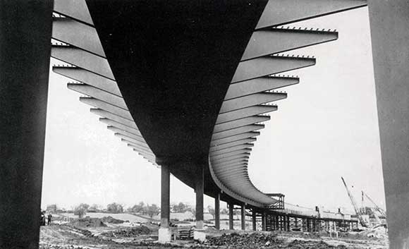
The underside of the viaduct, showing how the twin-tapered hollow box column piers support the spine beam and cantilevers.
When the 13½-mile length between Preston and Lancaster is completed next spring (1965), some 60 miles of continuous motorway will be available on the Lancashire section of the M6 North-South Motorway. This is the fourth section, the three finished and already in use being the 8-mile Preston By-Pass, the 12-mile Lancaster By-Pass and the 26-mile length running from the Preston By-Pass to the Thelwall viaduct. The only remaining work to complete the Lancashire section of the M6 will be a small length north of Lancaster.
A prominent feature of all motorways is the considerable number of bridges and the Lancashire section of the M6 is no exception, having a total so far of 169. A useful innovation is the painting of the steelwork on the many bridges in different colours.
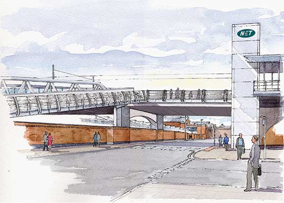
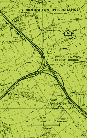
Under construction at the northern end of the Preston By-Pass is the Broughton Interchange, a three-level junction enabling the free flow of traffic between the North-South Motorway (M6) and the present A6 trunk road. This includes two bridges, ie the Fylde Junction Lower which will carry the Motorway over the link road serving traffic from the A6 and the Fylde to the south, and the Fylde Junction Higher which is to carry the link road serving traffic from the north to the A6 and the Fylde. This latter bridge passes over the M6 and the link roads from the A6 to the south and from the south to the A6.
 THE FYLDE JUNCTION HIGHER BRIDGE
The Fylde Junction Higher Bridge is a welded steel box girder viaduct supported on steel piers and having a curve length of 1,300 ft.; the width between parapets is 44 ft. It is in two continuous sections with an expansion joint over one of the central piers. The 715-ft. southern section consists of four 130-ft spans and two ends spans of 97 ft. 6 in., and the 585-ft. northern section is similar but has only three 130-ft. spans. The whole viaduct is on a horizontal curve of 1,164-ft. radius and the vertical profile has a 3.06% gradient for 790 ft. from the south abutment and then a 0.75% vertical curve over the rest of the structure. A constant super-elevation of 1 in 19.5 is applied across the carriageway and a fall in 1 in 36 to the hard shoulder.
The piers comprise 22 ft. 6 in. high twin welded mild steel hollow box columns 2-ft wide laterally and tapering from 7 ft. at the top to 4 ft. at the bottom longitudinally. The material is 1-in. thick and additional strength is provided by a 1-in. thick solid diaphragm down the centre.
Each pier is supported on a two-tier grillage encased in concrete integral with the pile cap. The lower tier comprises seven 27-ft. long 14 in. by 16 in. @ 158 lb. UC sections and the top tier two sets of three 24 in. by 12 in. @ 160 lb. UB sections, one set under each column.
Each hollow column is filled with concrete which is covered with a 1-in. thick stiffened plate. Another 1-in. thick plate over both columns forms the cap and provides a seating for the deck girder bearings, which are screened by steel box framing mounted on the cap plate.
The structural deck consists of a 14-ft. wide by 8-ft. deep three-cell welded steel box girder or spine beam running through the centre of the bridge with 14-ft. long cantilevers welded to both sides, generally at 10 ft. 10 in. centres, the whole supporting a reinforced concrete slab made to act compositely with the steel.
The box girder is of all welded construction in two continuous spans of 715 ft. and 585 ft. on the centre line. It consists of 1¼-in. thick top and bottom flanges in ND.1 steel and fours webs of ¾-in. thick mild steel plate dividing the girder into three cells of equal width. At each cantilever arm solid steel diaphragms are welded into the three cells. The diaphragms are generally of ¾-in. and ½-in. thick mild steel but over the piers and abutments where they act in bearing they are of 1 3/8-in. thick ND.1 steel. Flanges, webs and diaphragms are all stiffened where necessary and appropriate manholes are provided to give access to the whole of the inside of the spine girder.
The welded cantilevers are of mild steel, tapering from 5-ft. deep at the junction to 10 in. at the tip. The web is ¾-in. thick, the top flange is 12 in by 19/16 in. and the bottom flange is 9 in. by ¾ in. On both sides the cantilevers are shaped so that the top flanges follow the slope of the finished road surface. This entails a transition in the top flange of the cantilevers on the outside curve so that it meets the top of the box girder which has a horizontal top flange.
The reinforced concrete deck slab has a minimum thickness of 9½ in. and is generally reinforced with ¾-in. dia. bars at 4½-in. centres in both directions, top and bottom. It is covered with a waterproof membrane and 3 in. of hot rolled asphalt in two layers – a base course of 1¾ in. and a 1¼ in. thick wearing course. the carriageway is finished with ¾-in. green granite chippings.
The deck is supported on fixed bearings at the abutments and expansion bearings at all piers. The fixed bearings consist of mild steel bearing plates with rocker plates to allow for angular displacement. Two complete bearings are provided under the end of the box girder at each abutment and short 1-in. diameter prestressed bars resist uplift at the ends under adverse live load conditions.
Because of the very high loads expected on the expansion bearings to all piers, accentuated by the deck curvature producing eccentricity of loading, special ‘Hi-load’ bearings have been specified. A test load of 1,000 tons had been applied to these bearings, for each of which the maximum calculated load is 700 tons.
At the expansion ends of the deck girder two additional bearings of Meehanite metal type S.P. are used, in conjunction with four 11/8 dia. prestressed bars to resist uplift and, at the same time allow for movement due to changes in temperature.
Allowance for expansion is made where the two continuous girders meet over one of the central piers. Movement is accommodated generally by means of a toothed expansion joint of cast steel plates over the roadway, sliding plates at the verges and the stainless steel cover plates over the parapet plinths.
Fabrication and erection of the viaducts are of considerable interest. The columns for the piers and the cantilevers were completely shop welded but shop fabrication of the spine girder was limited to complete preparations of all diaphragms and web plates, the shaping of the flange plates to follow the curve of the viaduct, and their preparation for single-V transverse butt-welds, and the welding together of the two widths to form each length of flange. Flanges and webs were made in lengths mainly about 32 ft. 6 in long and they were cut to the nearest 9/64 in.
Erection and assembly of the deck steelwork were carried out on temporary trestles and bearer beams erected between the piers to form a working platform at the correct finished height of the bottom flange. Work started at the north abutment and followed four definite stages which were repeated throughout the length of the bridge.
Stage I
Bottom flange plates were laid in position on the bearer beams and pre-set to enable the single-V automatic butt welds to be completed.
Stage II
After the butt welds were cleared by X-ray, the flange was lowered to the correct level and bulb flats and central diaphragms tack welded in position, followed by inner webs, forming an egg crate construction. Vertical butt welds were then completed joining the webs longitudinally together and, following this operation, the internal fillet welding was commenced.
Stage III
This consisted of assembling the top flange plates in position, presetting to complete the transverse butt welds, lowering down to the correct level and welding to the webs and diaphragms.
Stage IV
This included fitting the cantilever arms, completing all internal welding and finishing the external cover welds.
To limit built in stresses, Stage II was never less than one plate behind Stage I, and the top flange remained unwelded on plate behind the vertical web plates.
The transverse welds in both flanges were carried out by automatic CO2 welding, the operator being protected from the weather by a sheeted steel framed housing mounted on wheels which was either rolled or transported by crane from each position to the next. All other welding was carried out by manual or semi-automatic CO2 process, the operator being protected during the placing of external welds between flanges and outer webs by a similar sheeted housing.
As erection of the spine girder proceeded, cantilever sections were raised on a lifting beam with trolleys attached, mounted on the top flange of the spine girder, and then rolled into position and welded to the spine girder.
Prior to delivery to site, all steelwork was blast-cleaned after fabrication and given one coat of protective paint. Treatment after erection consists of six coats of paint to all exterior surfaces and three coats to enclosed surfaces.
An interesting point in connection with the protection of the internal surfaces of the totally enclosed box girders is the use of silica-gel to reduce the relative humidity. Approximately 2,000 lb is distributed in bags throughout the length of the spine beam. Re-charging will be necessary only at three year intervals and thus maintenance painting costs for the interior of the girders will be negligible. This system is being adopted as a result of successful experiments with the box girders of the Samlesbury Bridge on the Preston By-Pass.
The Lancashire County Council is responsible for the whole Preston-Lancaster Motorway as agents for the Ministry of Transport. The design and contract for all the road and bridge works were prepared in the office of the County Surveyor and Bridgemaster, Mr James Drake, C.B.E., B.Sc., M.I.C.E., M.I.Mun.E., PP.Inst.H.E.
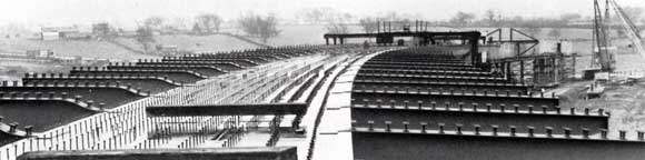
This illustration shows the top surface of the three-cell box girder or spine beam and the cantilevers forming the structural deck.