Technical
Composite slabs with in-plane loading
Although composite slabs are normally designed as one-way spanning and subject to (out-of-plane) gravity loading only, they often need to do more than this. Graham Couchman of the SCI discusses aspects of composite floor behaviour when subject to in-plane loading. The use of shear studs on non-composite beams is explained and justified, and guidance is given on how to design slabs subject to large in-plane forces.
Introduction
Two aspects of composite floors that feature behaviour that is sometimes not fully considered relate to edge beams that are designed non-compositely but are provided with shear studs, and the effect of in-plane forces in the slab due to diaphragm, or similar, action. These behaviours are considered below.
Edge Beams
At the SCI Advisory Desk we often get asked about the provision of shear studs on edge beams, where the studs are not needed to provide composite action for the beam, but rather to provide a structural connection to tie the slab to the beam. This makes sense, with detailing rules identifying any special provisions for slab geometry and reinforcement – U-bars must pass around the studs when the distance to the edge of slab is less than 300 mm, because straight bars would have insufficient anchorage.
Of course, even though the beam is designed to be non-composite, it doesn’t know that. Because the shear studs have some stiffness they cannot avoid attracting force as the concrete slips over the top of the downstand beam, so some composite action is going to be developed. A question then arises, do the rules for minimum degree of shear connection need to be satisfied?
To recap, the reason why all composite beams must have a minimum degree of shear connection is to ensure that there are enough studs (with a high enough collective stiffness) to limit the slip at the slab to beam interface. Rather than bothering designers with a need to explicitly consider stud stiffness, which incidentally will be between 50 kN/mm and 100 kN/mm depending on stud size and the slab, the rules for minimum degree of connection assure the provision of a certain level of resistance, to indirectly ensure the total stiffness of the studs present is sufficient. The rules presented in EN 1994-1-1¹, and previously BS 5950-3.12, were based on ensuring that the slip at the beam ends (where it is at a maximum) did not exceed 6 mm at ULS. More recent work, for example the more relaxed rules in SCI publication P4053, recognise that in some situations the stud resistance can be maintained to higher levels of slip. For example, in the presence of transverse trapezoidal decking 10 mm can be achieved. An ability to accommodate greater slip means that fewer studs are needed, because their collective stiffness can be lower. It is worth adding that in addition to needing slip capacity, studs must be stiff enough so that the slip at SLS levels of loading is sufficient to mobilise the shear studs, and therefore justify use of their resistance in design. A shear connector that lacked initial stiffness might have a high resistance, and indeed high slip capacity, but slips would never be high enough to make it ‘work’ properly. Generation 2 EN 19944 addresses this particular aspect by introducing a number of different ductility classes, compared to the previous ductile/non-ductile ‘switch’.
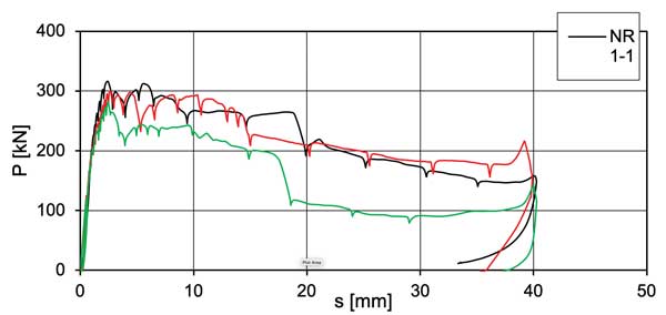
All this would make one believe that the minimum degree of shear connection rules should be satisfied, even for beams that are designed to work non-compositely. Failure to do so would result in the studs ‘unzipping’ as the end slip exceeded their slip capacity as load was increased. However, consideration of the load-slip behaviour for a shear stud, typically determined by a push-out test (Figure 2a), shows us why this is not in fact the case.
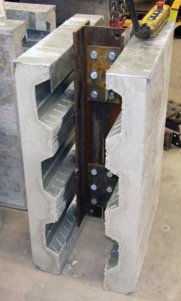
Figure 2b shows that although there is a value of slip beyond which the stud resistance reduces (for these curves, which were for specimens with transverse trapezoidal deck, a slip of between 10 and 15 mm), it is not a brittle fall-off. The curves in Figure 2b show that the test set-up only allowed slips of up to 40 mm to be recorded (this would have been the distance that the steel section initially protruded above the slabs, see Figure 2a).
EN 1994-1-1 defines behaviour from a load-slip curve in terms of:
- Characteristic resistance is the minimum failure load (from a group of three tests) reduced by 10%
- Provided the deviation of any single result does not exceed the mean of all tests by more than 10%.
- The slip capacity of an individual test is the maximum slip at the characteristic resistance, and the characteristic slip capacity is the lowest slip from a set of three tests, reduced by 10%.
Beyond the characteristic slip capacity, the characteristic (and therefore design) resistance of the stud cannot be assured. But of course if the beam has been designed to work non-compositely, then it doesn’t matter if the stud cannot provide its design resistance. All that matters is that it remains attached to the beam, and so continues to tie the slab to the beam. For the example curves shown in Figure 2b this would remain the case for slips up to 40 mm. Taking the extreme case of zero collective stud stiffness, slip would not be expected to exceed such a value. This qualitative conclusion has been quantified by researchers in the past, for example reference 5 used numerical analysis to predict 15 mm slip for a typical size beam over a 15 m span. This finding can also be confirmed by considering the elastic behaviour of a beam, given the radius of a beam in bending R = M/EI, and using this radius to predict end slope and thereby the shortening of the top of the beam. It can also be understood by the analogy of bending two rulers, one placed on top of the other. For ‘one foot’ rulers one would find approximately 1 mm slip – zero shear connection stiffness does not result in infinite slip.
The studs on an edge beam that tie the beam to the slab transversely will be subject to a combination of shears in two directions, and some interaction that would potentially reduce the shear resistance can be envisaged. For beams that are designed to be non-composite this is irrelevant. For the alternative case where the edge beams (or others) are designed to be composite, EN 1994-1-1 6.6.4.3 provides an interaction equation:

For beams supporting composite slabs with trapezoidal decking this may be conservative, given that in the direction of the decking ribs the concrete near the base of the studs is critical, but in the orthogonal direction failure is normally due to failure of a concrete surface passing over the studs.
In-plane diaphragm action
Turning to the slab, there may be a concern that a slab that is loaded in-plane, in whatever direction, may experience different stresses at the interface between the decking and concrete compared to a slab loaded purely in bending. It is easy to imagine that a slab that was lozenging would have a tendency to break the shear bond. Provided in-plane stresses and strains are small, practically it is suggested that such effects can be ignored. The tests used to determine shear bond include a cyclic element to destroy chemical adhesion, so the shear bond used in design is solely due to mechanical interlock and one would expect this to be sufficiently robust.
In extreme cases a slab may be subject to significant in-plane, and coincident out-of-plane, loading. The former could be due to thermal movements. Little is known on how composite slabs would then behave. For example, the shear bond would presumably be adversely affected if the concrete was in tension, and therefore cracked, throughout its depth. In a standard test to determine the level of shear bond that can be generated by a given deck, whilst the extreme (lower) fibres of the concrete will indeed be in tension, those above the deck neutral axis will not. Evidence suggests that much of the shear bond generated by trapezoidal decks is due to the embossments and form of the top flange of the decking. In the absence of any evidence from testing or numerical modelling, the most robust approach in such a situation could be to:
- Design the slab as a reinforced concrete element carrying coincident in-plane and out-of-plane loading
- Use the decking as permanent formwork (ignore any shear bond)
If necessary the decking could also be used to add to the vertical shear resistance of the slab. Its ability to contribute has recently been recognised during the process of developing the Generation 2 EN 1994. The relevance of it being able to do so would be particularly high in slabs that had in-plane tension, the presence of which reduces the shear resistance of the concrete (which is the only contributing element according to the current EN 1994 rules, which are taken from EN 1992).
Conclusions
As engineers we often use our judgement to make pragmatic decisions, and one common example has been the use of apparently insufficient shear studs on non-composite edge beams. No matter what we assume, in this case that the beams are non-composite, the physics of elements with stiffness attracting load cannot be ignored. The discussion above shows why the approach of seemingly adding too few studs can indeed be justified. Consideration is also given to composite slabs in which significant in-plane forces coincide with out-of-plane loading, with a conclusion that such slabs should not be designed compositely (using available shear bond data) without justification. A traditional reinforced concrete approach should be adopted.
- BS EN 1994-1-1:2004. Eurocode 4: Design of composite steel and concrete structures. General rules and rules for buildings. BSI, 2005
- BS 5950-3.1:1990+A:2010. Structural use of steelwork in buildings. Design in composite construction. Code of practice for design of simple and continuous composite beams. BSI, 2010 (Superseded).
- P405. Minimum Degree of Shear Connection Rules for UK Construction to Eurocode 4. Graham Couchman. SCI, 2015.
- prEN1994-1-1. Project Team Final draft April 2021 (this document is not publicly available)
- Composite Construction in Steel and Concrete V. Edited by Roberto Leon and Jorg Lange, ASCE, 2004.