Projects and Features
CAD is just the ticket for new bus station

The 3D models show every steel member
Barnsley’s new centrepiece transport interchange required some intricate 3D modeling to create a complex steel design. Martin Cooper reports on how the detailing worked out.
FACT FILE: Barnsley Transport Interchange, Yorkshire
Main client: South Yorkshire Passenger Transport Executive
Architect: Jefferson Sheard Architects
Structural engineer: Arup
Main contractor: Laing O’Rourke
Steelwork contractor: Billington Structures
Project value: £24m
Steel tonnage: 650t
Think of Barnsley and the surrounding South Yorkshire region and you probably think of coal mining and heavy industry. Although the town of Barnsley can lay claim to being mentioned as far back as in the Doomsday Book, it owes its relative prosperity and importance to the Industrial Revolution of the late 18th Century.
From then on coal mining was the main employer in Barnsley, and it also provided the power for the other principle industries in the area, glass blowing, textiles and steel.
However, since the infamous strike of 1984, the coal industry has shrunk to the point where today there are no mines in the area. To combat this Barnsley has embarked on an ambitious programme of redevelopment under the banner ‘Re-making Barnsley’.
Over the coming years the entire town centre will be transformed with one of the most integral elements of the programme being the redevelopment of the bus depot which adjoins Barnsley railway station.
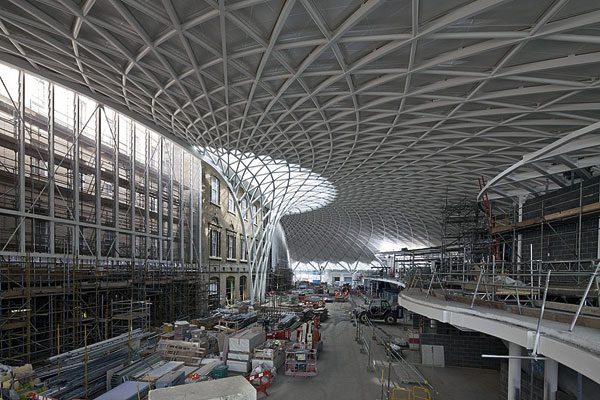
The overall concept is to develop a better interchange between rail and bus, while integrating a new landmark building into the town centre. Project architects Jefferson Sheard says it will be achieved by providing a high quality, fully enclosed ‘glazed street’ which will link into future developments in the Barnsley masterplan.

The overall design has been described as ‘swan-like’

Steel allowed for the open-plan concourse design

The building is a two-storey structure

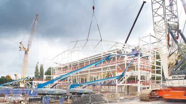
Curved beams created a challenge

13 pairs of glulam beams support the roof in part

Supporting trusses are arranged along the upper level

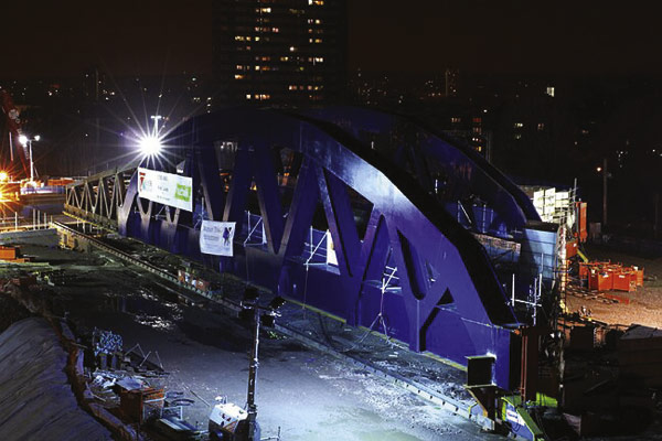
The bridge connects directly into the railway station
To create the desired landmark structural design, the architects and engineers – Arup – came up with a building based on an extremely complex geometry. Billington Structures’ Strucad Detailer Glyn Bassindale explains: “The geometry is very complex and could only have been done with the aid of 3D computer design.” In fact Mr Bassindale adds the design is so complex it took eleven months to draw and five months to actually set out the 3D model.
Caroline Thomas, Arup’s Structural Engineer comments the design was challenging because so much of the internal steelwork is needed to be exposed and a lot of effort had to be put into its appearance. “There are also a vast amount of interfaces and connections to make the complicated shape. Plus there are just so many different members to integrate, it was certainly a team effort to make the model,” she adds.
Once the 3D model was created it not only showed intimate details of the project, including every steel member, but it allowed the viewer to turn and twist it, to give views from every angle.
Billington Structures’ Project Manager John Batty says the 3D model has ultimately speeded up construction of the project. “By creating the model the many sub-trades were sent the programme and could see exactly where their materials would be needed before the job even started,” he says. “The model also eliminated the need for hundreds of drawings.”
Described by Mr Batty as one of the most complicated structural designs he’s ever worked on, the Interchange has four basic elements: the entrance; two concourses and a bridge which links into the adjacent railway station.
“It’s swan-like,” is how Mr Batty describes the unique shape of the structure. “If you look at the bridge as being the creature’s neck, the two concourses – which are elliptical aerofoils – as the swan’s wings, while three cones on the central entrance create a wave humpback effect much like a bird’s shoulders.”
Integrating all of these features was time consuming enough, but as Mr Bassindale explains what also makes the structure’s design so complicated are the amount of curves.
“The entrance curves in three directions,” he says. “And the main concourse aerofoil elliptically curves on to the bridge.”
Overall the Interchange is a steel framed two storey structure 155m-long and 64m wide – from the entrance to the end of the bridge – and with a maximum height of 14m.
From the town centre the Interchange is arranged so that passengers can walk into the entrance, which is situated on an intermediate level, and then either descend stairs to the ground level bus concourses, or ascend stairs or elevators to the first floor retail area and the bridge which links directly into the railway station.
Because of space constraints the two concourse wings differ in length and structure. The south wing consists of eight curved grids measuring 9.6m x 8.6m, while the north wing is straight with three similar spaced grids and then a curved coach station canopy on the end.
Arranged along the concourse are five kidney-shaped retail pods – A, B and C in the south wing and D and E in the north. The two-storey pods will house retail outlets, except the one-level E pod which is a toilet block, and they vary in size with C being the largest at 8m x 23.5m.
Mr Batty says the pods differing sizes and make-up was yet another challenging aspect of the job. “We had to make sure each individual curved beam was ready for the erection process and this meant closely liaising with our sub-contracted steel benders.”
Holding up the roof in part above the inter-connected pods are 13 pairs of raking glulam timber beams. The inner beam of the pair is 4.5m-long, while the outer raking beam measures 7m.
Also supporting the roof and the three shoulder-like cones (formed by the geometry of the roof) are two large trusses which sit above the Interchange’s main entrance. The largest truss weighs 4t and is 22m-long, while the second is 3.6t and 18m-long. Both were fabricated and lifted in to position in one piece.
Along the rest of the two concourses roof are a number of smaller supporting trusses made from 9.7m long curved tubular steel members. These support a v-shaped Delta beam made from four plate girders which will remain exposed. Once steelwork is complete the roof will be clad with transparent air-filled cushion cladding.
Another major challenging element of the project is an architectural steel feature wall which partially wraps around pod E and interconnects with the roof. “The wall isn’t integral to the structure, it purely a feature and is intended to give people something interesting to look at when they approach the Interchange from Barnsley’s main shopping thoroughfare, Regent’s Street,” Mr Bassindale says.
The wall is 16.5m high and is curved on plan and tapered in section with a length of 15m. Fabricated from sections of cold rolled steel, it will be clad with exposed copper.
In total Billington will install more than 27t of cold rolled steel, most of which will be used as an underlay cladding for the structure and bridge and support the exposed copper finish.
The connecting bridge which traverses the bus parking area is fabricated from two 914mm x 419mm spine beams and seven 200mm x 100mm box section hoops and is supported by one 805mm diameter CSH column.
Mr Bassindale sums up the project as one of the most challenging and says only steel could have been used to create the desired structure.
When it opens in February 2007, Barnsley will have a bus station fit for the 21st Century and the town’s on-going redevelopment and renaissance.
The 3D view aids design
Everyone who worked on the design of the Barnsley Interchange project says it wouldn’t have been possible without the aid of 3D computer design. “The job is just so complex, I don’t think it could have been done on a drawing board,” Mr Bassindale suggests. “Certainly not by me.”
He has been with Billington Structures for more than ten years and says he joined the design department at the end of the ‘drawing board era’. Since then computer design packages have become the norm and have really opened up the floodgates in terms of what can actually be produced, he adds.
")
")
“Ten years ago structural designs may have incorporated features such as curved canopies or some other similar feature, now we’ve really moved on and wave-forms are appearing as roofs and architects have been given far more freedom working in 3D,” Mr Bassindale says. “Everything now is architecturally driven, design wise.”
Caroline Thomas at Arup agrees and says designs such as the Barnsley job are certainly becoming more common before adding: “Designing the V-shaped Delta beams used on the project would have been very difficult without the aid of 3D. As it was they were extremely challenging.”
There are a number of 3D modeling packages available, but Billingtons used the StruCad detailing system from AceCad. Andrew Manze, Head of Sales for AceCad says this system offers a fast and accurate methodology and importantly allows the user to not only produce an initial 3D model, but also produce 2D CAD drawings without any extra set-up.
“These would ordinarily be used in workshops and fabrication yards,” Mr Manze explains.
On the subject of what the future may hold, Mr Manze suggests that architects are now designing more complex structures safe in the knowledge that packages such as StruCad are continually evolving to allow steelwork fabricators and structural engineers the ability to model more and more complex designs.
Tom Rhys Jones, Managing Director of architects Jefferson Sheard doesn’t wholly agree, but does say building design has moved on during the last few decades and projects such as the Barnsley Interchange would have been a huge headache without 3D modeling.
“We don’t design complex projects just for the sake of it, but 3D does make it easier for engineers to design them,” he says. “However, the bottom line is the client has got to want a particular structure and people do place more value on design nowadays.”