Technical
AD 305: Stiffness and Rotation of Moment Connections
The issue of connection stiffness and rotation for bolted end-plate moment connections arose recently at a connection workshop and concerned the stiffness of a cantilever bracket connection up to ultimate limit state.
Connection stiffness and rotation are very well covered in the opening chapters of Joints in Steel Construction: Moment Connections, (SCI-P- 207) which should be consulted for a full treatment of the issues, particularly section 2.5. Section 2.5 offers guidance as to the importance of connection stiffness in relation to various types of structure. Figure 1 shows typical cantilever bracket connection details.

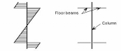
Figure 1: Typical Cantilever Bracket Details
When an infinitely rigid joint carries load its members and connection rotate as shown in figure 1a. The members at a theoretically rigid joint remain at the same angle to one another after the application of load. However, when the connections in a frame are not fully rigid an additional rotation Ø between the members also occurs, as shown in Figure 1b.
This additional rotation is plotted in moment rotation curves for the classification of connections. Ø would be zero for a fully rigid connection, but this will not be achieved in practice. In some cases, the additional rotation and resulting frame deflections due to Ø must be accounted for and section 2.5 of SCI-P-207 offers advice.

Figure 2: Failure Modes for Bolted End-plate Moment Connection
Figure 2 is taken from SCI-P- 207 and shows the 3 possible failure modes that may occur in a bolted end plate moment connection. The traditional British approach (Section 2.5, SCI-P- 207) to achieving steelwork connections that are designed to be fully rigid up to ultimate limit state is to ensure that Mode 3 is the critical mode of failure for the connection. In simple terms, mode 3 is bolt failure and is usually achieved by making the end plate thickness not less than the bolt diameter on the beam side.
The welds, webs, flanges and end plates etc are designed to carry forces at least equal to the bolt capacities, ensuring that the bolts are the weakest link. On the column side of the connection suitable tension, compression and shear stiffeners may have to be added to ensure that the bolts are the weakest link. If both the beam end plate and column flange thicknesses are greater than the bolt diameter, the normal plastic bolt row force distribution is modified to a linear distribution in accordance with step 1C of SCI-P- 207 in determining the moment of resistance of the connection. Moreover, it is necessary to limit the column web panel shear to 80% of the column capacity or provide suitable stiffening if this is not possible.
According to SCI-P-207 when the above provisions are complied with it may be assumed for design purposes that the connection is fully rigid and the effects of joint rotation are small enough to be ignored. Only in very special cases will it be necessary to account for the value of Ø in structural calculations.
Contact: Thomas Cosgrove
Email: t.cosgrove@steel-sci.com
Tel: 01344 636555