Technical
AD 275: Columns in Simple Structures BS 5950-1: 2000 Special Design Cases
Following a number of questions about special design cases concerning columns in simple structures this AD Note provides guidance on the design procedure for the special cases that sometimes arise with columns in simple structures.
Clause 4.7.7 in BS 5950-1: 2000 outlines the design rules for columns in simple structures. This is a safe and easy-to-apply design method that is intended for the majority of columns in simple structures. In this method it is assumed that the column is at least held in position at each floor level in two perpendicular directions and the only moments that arise are due to the nominal moments applied to the column by the simple beam end connections. In most cases the values of the nominal moments are calculated from the assumed 100 mm eccentricity of the beam end reaction – see Clause 4.7.7.3. Clause 4.7.7 indicates how the net nominal moments at any level are distributed in the column and the effect of pattern loading on the column need not be considered with this safe, simple method. In addition, it is further assumed that the column is in double curvature – the bending moment diagrams for the columns are of the “cross-over” type with the end values of approximately equal magnitude. However, it is not necessary to know the exact shape of the column bending moment diagram to apply the method.

Fig. 1. Typical BMD for column in a simple structure
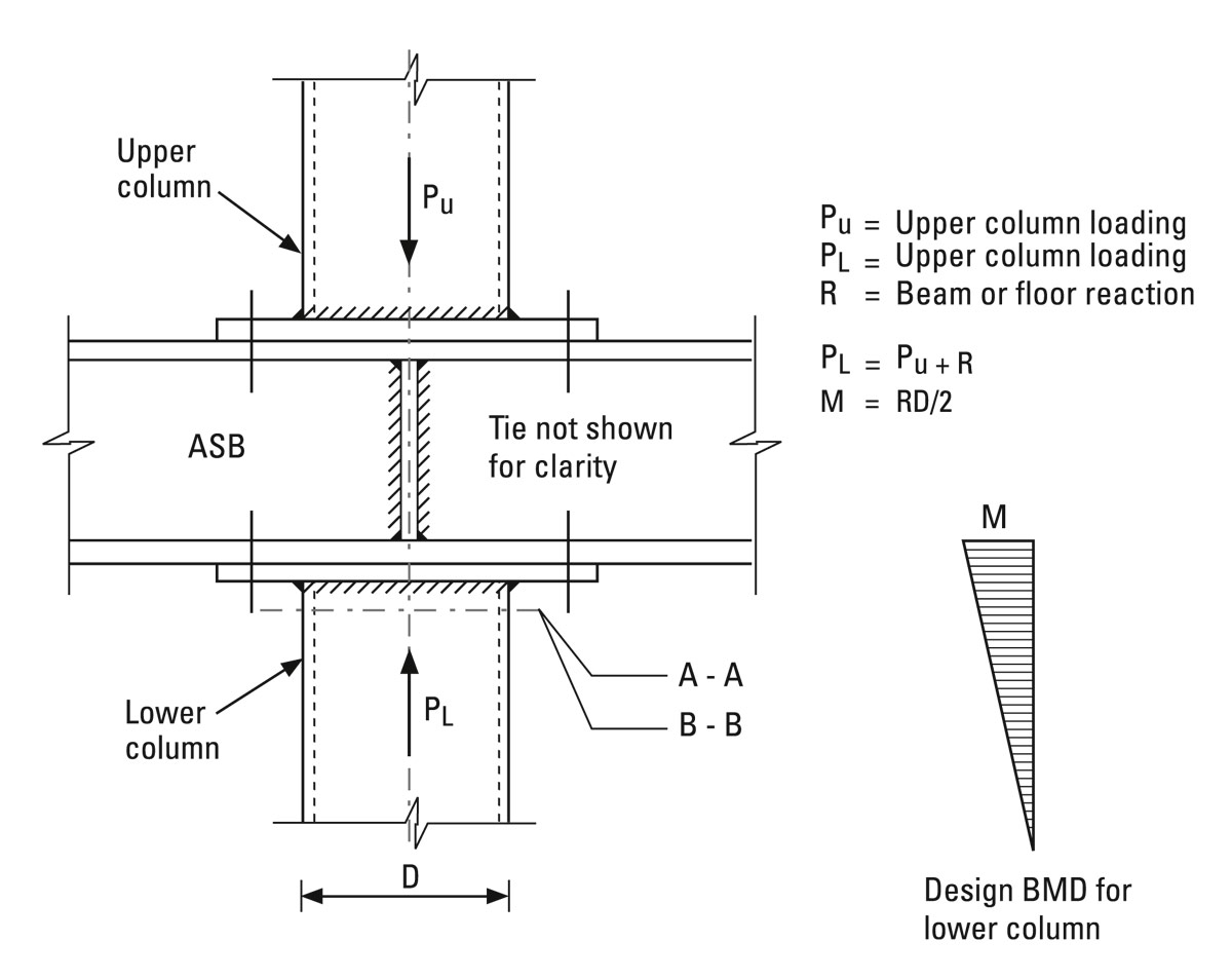
Based on these assumptions an equivalent slenderness λLT of 0.5 L/ry may be taken for double symmetric cross-sections and the single interaction relationship in Clause 4.7.7 need only be satisfied, utilising Mbs. It is recommended that when the assumptions that underpin this method are satisfied the design approach of Clause 4.7.7 should be followed. Unfortunately, not all columns in simple structures satisfy the above assumptions and some special cases arise. The more obvious case is where additional moments are applied to the column; for example, from a cantilever, lateral loading, or an edge beam which carries external cladding in bending and torsion and transfers an end torque to the edge column as a moment. In these special cases, the column should be designed in accordance with section 4.8.3 and thus, three interaction equations must be complied with. First, a cross-section capacity check from 4.8.3.2 is required and second, at least two member buckling resistance checks from 4.8.3.3.1, 4.8.3.3.2 or 4.8.3.3.3 are required. The equivalent uniform moment factors, m, are obtained from either Tables 18 or 26 as appropriate and the effect of pattern loading on the column needs to be accounted for, owing to the more sophisticated checks in section 4.8.3. The shape of the column bending moment diagram (required to obtain m values) is derived by combining any additional applied moments with the distributed net nominal moments. The beam reactions are assumed to act at the eccentricity in 4.7.7.1, 4.7.7.2 or 4.7.7.3, but usually at 100 mm from the face of the steel column.
In summary, it is recommended that columns in simple structures should be designed to Clause 4.7.7 where possible. However, when special cases arise the column must be designed to section 4.8.3 taking account of pattern loading and the nominal moments calculated from the eccentricities from 4.7.7.1, 4.7.7.2 or 4.7.7.3 as appropriate.