50 & 20 Years Ago
40 Years Ago: Digital computer reduces design time for the British Pavilion at Montreal
Taken from Building with Steel, 1967

The British pavilion occupies three acres and uses nearly 1,000t of structural steelwork

The Universal and International Exhibition of 1967, known more colloquially as ‘Expo 67’ is part of Canada’s Centennial Celebrations. The Exhibition is due to open in Montreal for six months from April 1967. The 1,007 acre site is spread over three main areas, the Ile Sainte Hélène, Ile Notre Dame and the Mackay Pier, all in the St. Lawrence River. It has been estimated that about 30 million people will visit the exhibition during its six month’s run and that on peak days attendance will be in the region of 350,000.

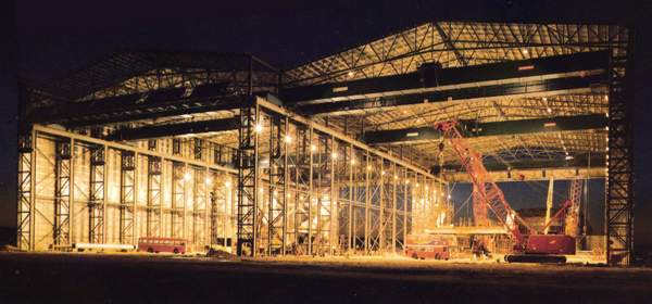
The tower erected and the sheeting being added

Ile Notre Dame – Expo 67 takes shape
The British pavilion sits on a three-acre site on the Ile Notre Dame. Reminding visitors that the British are an island people, the cliff-like walls rise out of the water. The mass is big, with exhibition halls deeply cantilevered over moats and the site dominated by the tower.
The tower is a 202.5 ft tall 12-sided truncated tapered structure founded at a level of 50.00 O.D., the highest point being at a level of 252.5 O.D. The external width of the base is approximately 90ft reducing to about 54 ft at roof level, itself about 60ft below the highest point of the shell. The structure has a main internal floor at the level 73.00 O.D. and basically forms a hollow shell some 120ft in height up to the flat roof level. An intermediate platform between the main floor and the roof is suspended by rods from the sides of the structure. The steelwork is clad externally with asbestos cement sheeting and provision is made for an internal lining. The main floor is constructed of 4-in. thick concrete slab carried in metal trays supported by the structural framework.
It was decided that the most economical design could be developed in the time available only by the use of computer methods of analysis. Accordingly, arrangements were made with Prof. M. R. Horne of Manchester University to use the programme ‘Lineal Analysis on Plane Space Frames’ produced by his department to run on their computer. very approximate calculations were made for the steel framework and sizes selected therefrom. An intermediate bicycle wheel diaphagm was added to the tower frame at this stage, but once the computer analysed the preliminary sizes against the loading conditions, it was decided this was uneccessary. The suspended platform was not finalised until a late stage in the design. The ring beam was made fully rigid and designed to take the torque from the platform – here again the use of the computer proved invaluable.

The Indians of Canada’s 100 ft high steel teepee

The USA’s geodesic dome – 275 ft in diameter, constructed from steel, aluminium and clear plastics

The USSR – a 100,000 ft2 steel roof on 450 ft exposed vee-shaped steel supports

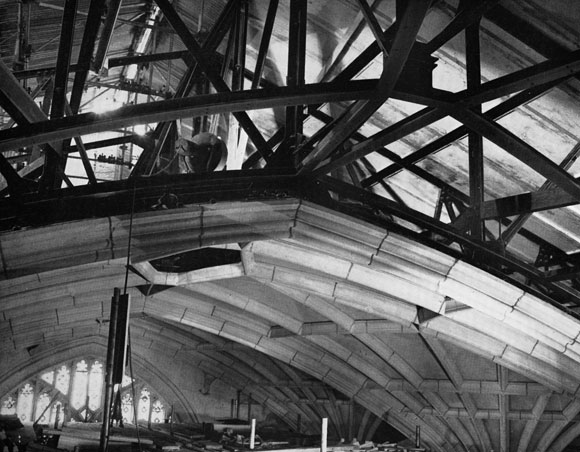
The suspended platform on trial erection at the fabricator’s works

The suspended platform on trial erection at the fabricator’s works