Projects and Features
The Lyric Theatre, Wales Millennium Centre
A steel structure was chosen for this theatre. In the past theatres have nearly always been made of concrete.
Client Wales Millennium Centre
Architect Percy Thomas Partnership
Structural engineer Arup
Steelwork contractor Watson Steel
INTERNATIONAL competitions were held in the summer of 1996 to select a design team for the 33,000m² Wales Millennium Centre (WMC), which will act as host to eight resident cultural and arts organisations, the best known being Welsh National Opera.
But it took almost six years to bring the project to site, a period of almost continuous re-design in order to reconcile ambition with budget and to give the funders and tenants the confidence that the business plan was robust and sustainable.
Construction began in February 2002, steel erection began in May 2002 and the topping out ceremony was held in March 2003. Completion is scheduled for September 2004.
THE AUDITORIUM
The brief for the auditorium required it to be used for opera, ballet, large scale dance, musicals and variety, with as secondary uses: children’s musical theatre, comedy and large scale concerts. The design that evolved provides up to 1,852 seats, arranged on a stepped stalls level and two upper balconies. Narrow sideslips and boxes occupy the sides of the auditorium and link the stage to the audience, which is essential for the intimacy required by opera.
THE FOUNDATIONS
The design of the foundations was influenced by the need to avoid buried dock structures and the prevention of noise being transmitted into the auditorium from an adjacent road tunnel. Also, the decision to locate the new National Assembly for Wales across the road from the WMC site necessitated changing the 750 piles from driven to continuous flight auger as they are quieter to install.
THE SUPERSTRUCTURE
The superstructure is physically divided into a number of structurally separate buildings, for both conventional structural reasons and also to prevent unwanted noise (plant-induced, for example) from being transmitted by the structure into the theatre.
The building is a tight fit of structure, architecture, building services and theatrical systems. Storey heights are not large and many areas, having no external walls, are highly serviced. Major plant is located close to its load centres but nevertheless there are still big risers and duct runs to be integrated. Computational fluid dynamics analyses provided confirmation that air and smoke movements would be as the designers intended in the large volume spaces. They also enabled significant savings to be made in the sizing and costs of the smoke extract plant and ductwork.
STEEL STRUCTURE
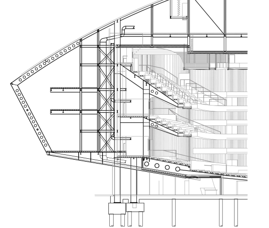
- It was often thought that, because of the complicated geometries of balconies and the need for massive walls, theatres were best constructed from in-situ reinforced concrete. This was challenged by Arup-engineered theatres in Escondido, California and New Jersey (ref. 1). The American experience showed that steel-framed construction was a credible alternative to concrete, with floors constructed of a mixture of normal and lightweight concrete cast on profiled metal decking. This proved practical, even in regions of changing three-dimensional curvature, such as the theatre balconies (fig. 1). It offers four significant advantages, all of which were important for the WMC.
- The speed with which the primary frame can be erected and made watertight, allowing early commencement of the installation of services, theatrical equipment and interior finishes.
- The design of the structure can be, at the right stage, separated from the continuing development of the form of the architectural and acoustical walls, which are constructed out of blockwork. The frame can then be fabricated and erected in parallel with the developing architectural and acoustical design.
- The construction requires fewer people working high above the ground for a shorter time than with a reinforced concrete frame.
- A steel-framed building is usually lighter than a concrete-framed one and foundation economies can also be realised.
VIBRATION
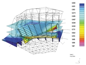
Being lighter, a steel frame may be more susceptible to vibration than a concrete one. Of particular concern in the WMC were the main theatre balconies, which cantilever up to 10m from their supporting columns, and the cantilevering foyer floors at the front of house. Detailed threedimensional vibration analyses of the cantilevering structures verified that their response to footfall would be acceptable (fig. 2).
ROOF
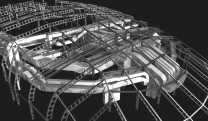
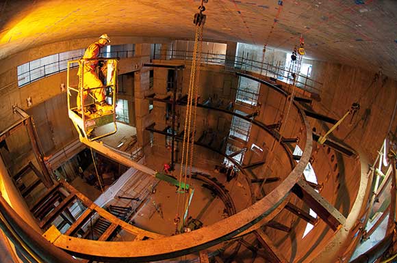
Storey-deep steel trusses span the roof of the auditorium. The upper booms of these trusses support a slab of concrete on profiled metal decking. The lower booms support precast concrete panels with an in-situ topping, which form the ceiling to the auditorium. Between them, the two slabs provide the acoustic isolation necessary to prevent the noise from aircraft disturbing the theatrical or operatic experience. The space above and between the two slabs is occupied by enormous ducts which supply large volumes of low velocity air to underseat air terminals in the theatre and then exhaust the vitiated air through the ceiling (fig. 3).
FLYTOWER
The flytower is connected structurally to the main body of the auditorium. It is separated for acoustic reasons from the back of house structure, which supports the air handling plant. Almost every piece of steel within the flytower is positioned to the millimetre by the needs of the systems which raise and lower scenery, both the present manual systems and the future mechanical systems. The walls of the flytower are clad in a mixture of blockwork and dry lining.
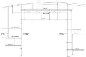
Suspended within the flytower are the gridiron and a series of narrow galleries, which run from front to back at each side. Supported by the rear face of the flytower and by hangers from roof beams which cantilever beyond the rear face of the flytower are a series of crossover galleries. Cantilevering from the inside of the front face are a series of narrow platforms known as perches. Also suspended from the bottom flanges of the twin cellular roof beams are pulleys over which run the cables by which scenery is raised and lowered during performances. Horizontal reactions at the pulleys are braced by horizontal UC sections, which connect the bottom flanges of the cellular beams (fig. 4).
There are major openings in the flytower structure at stage level on three sides. Trusses within the flytower walls carry gravity loads over them (fig. 5).
STIFFNESS
The flytower columns are about 35m tall and heavily loaded, with design axial loads approaching 11,000kN. Where there are floors that frame into the faces of the flytower the buckling lengths of the columns are conservatively taken as the storey heights. However, in other locations, especially the rear face, floors do not frame into the face of the flytower. The columns are braced only by the spring stiffnesses of elements (beams with horizontal webs or rear crossover galleries or perches) which frame into them. It was therefore necessary to adopt an analytical method which could demonstrate that their performance would be satisfactory. We used OASYS GSA’s ‘Buckle’ module to calculate, for each column, its λcrit, its modeshape and the forces and moments associated with a maximum buckled column displacement of 1m. We then assessed initial imperfections in the columns and factored the results of the ‘Buckle’ analysis by the ratio (initial imperfection/1m)*(1/(λcrit-1)), and checked displacements, forces and moments in the columns and members which restrained them.
CORROSION AND FIRE PROTECTION
Fire and corrosion protection of the steelwork could have been expensive and time-consuming. Corrosion protection was eliminated almost everywhere, on the grounds that the steel was going to be in a dry internal environment. The only exceptions were steelwork that remained visible, such as the gridiron and galleries in the flytower, and steelwork in damp locations such as uninsulated rooftop plant rooms and external wall cavities. There was one unexpected disadvantage of this approach: the contractor’s project manager remarked that he wished he had painted all of it, because of the volume of questions he had to field about the rusty steelwork.
Much of the vertical structure is fire-protected by being encased in blockwork walls. The remainder is fire-protected by dry lining. For the horizontal structure we adopted, with the agreement of Cardiff Building Control, a fire engineering approach. Finite element analysis of the floor structure under fire conditions identified the inherent fire resistance in the beams, and additional fire protection was only provided if the inherent fire resistance did not match the period that was required. This eliminated considerable quantities of fire protection.
References 1. Chan, J., Gautrey, J., Hamilton, N. and Locke, A.: New Jersey Performing Arts Center. The Arup Journal, vol. 33, no. 1, 1998.
Chris Jofeh, Director of Ore Arup and Partners


