50 & 20 Years Ago
Rio-Niteroi Bridge

From Building With Steel, September 1974
An important aspect of Brazil’s rapid redevelopment in the 1970s was the provision of a road network. Part of this was the 4,000km highway linking the cities and town of the east coat. Shortcutting a 90-mile detour round the bay is the new Rio-Nieroi bridge. The centre section consists of steel box girders and T. J. Upstone MSc, FICE, of RDL Ltd described the design and construction in this article.
Guanabara Bay at Rio de Janeiro is one of the largest natural harbours in the world. Its entrance is comparatively narrow and flanked on either side by steep mountains. The most famous of which is the Sugar Loaf. The city of Rio de Janeiro was founded in 1565 by the Portuguese. They chose the level land between the mountains and the shores on the western side of the mouth of the bay. Development and expansion of the city spread between the bay and the mountains. Eventually the town of Niteroi was founded on the eastern side of the bay opposite Rio.

Developments have used up nearly all the available· land in the Rio area sandwiched between the bay and the mountains. Niteroi has developed to supply this lack of space. Concurrently the transport of passengers and vehicles across the bay has increased enormously. The passenger ferry boats are large, frequent and efficient, carrying 2,000 people each. The vehicles wishing to cross are however not quite so well served and at weekend peak periods long queues of traffic build up. The alternative to crossing the bay is a 90 mile detour around the north end of the bay. Access to the countryside east and north-east of the bay is also obtained through Niteroi. The bridge is also part of the 4,000km highway which links the towns and cities that lie along Brazil’s eastern coast.
The consulting engineering firm of Howard Needles Tamman and Bergendorf from Kansas City Missouri made a study and proposals for a road bridge crossing the bay linking Rio and Niteroi for the Brazilian Road Board.
The shortest distance between the two cities would be 5 kilometres. This line would inevitably run very close to the domestic airport of Santos Dumont. The navigation headroom required was 65 metres. To attain this height the bridge would inevitably be in the flight path of the airport. So the bridge line had to be pushed further away from the airport. This lengthened the bridge to a total of 11 kilometres. Even in this position the height of the bridge was limited to 77 metres above water level to be below the flight path of the airport.
The design of the six lane highway bridge included high level steel box girder spans over the navigation channels, approach spans over water of prestressed concrete construction, a prestressed concrete viaduct, segments through two of the islands in the bay, toll booths and administration facilities.
Howard, Needles Tamman & Bergendorf were responsible for the design of the steel navigation spans and their supporting piers. Escritorio Antonio Alves de Noronha (Brazil) was responsible for the approach spans and their foundations.
The first designs by the American consultants utilised TI and other special American steels. These designs were modified to suit available British steels.
The contract for fabrication and erection was awarded to a Joint Venture of Redpath Dorman Long (Contracting) Ltd. and the Cleveland Bridge and Engineering Company Ltd. The Brazilian firm of Montreal Engenharia SA was associated with Joint Venture for the works carried out in Brazil.

The centre span of 300 metres is flanked by 200 metre sidespans. These side spans are cantilevered a further 30 metres into the approaches. Steel spans of 44 metres are suspended between this steel· cantilever and a concrete cantilever projecting from the concrete approach spans. The aerial restriction eliminated a cable stayed or suspension bridge solution, thus the bridge is a continuous box girder: The 300 metre span is the longest girder span in the world.
The cross section is of twin box girders 6.8 metres wide. Their depth is 13 metres at the haunches reducing to 7.5 metres at the centre of the main span. The six lane 25.9 metres wide orthotropic deck is stiffened with longitudinal trough sections. The webs are stiffened with longitudinal bulb flats and the lower flanges have ordinary flats and bulb flats as longitudinal stiffeners. Heavy transverse frames occur at 5 metre centres on the webs and lower flanges in line with the deck cross girders. Cross bracing both inside the boxes and between them occurs at 15 metre distances.
The orthotropic deck thickness varies from 10mm to 25mm. The lower flange varies from 10mm to 45mm whilst the webs are from 12mm to 18mm. Grades 43A, 50C and 55E steels to BS 4360 were used. The total weight of steel is 13,100 tonnes of which nearly 8,000 tonnes is high yield grade 55E.
The steelwork, which is all welded, was fabricated in the UK, generally in the form of stiffened plate panels for eventual assembly into box girders at the site. Exceptions to this form were the bearing areas. Here because of the complex stiffening arrangements a complete slice 4 metres wide from each girder was fabricated in one piece.
A ship was specially chartered to transport the steel work to Brazil. The Carolina made eight voyages carrying up to 2,000 tons of steel from the Tees direct to the working site on the Island of Caju in Rio Bay without any transhipment or further handling.
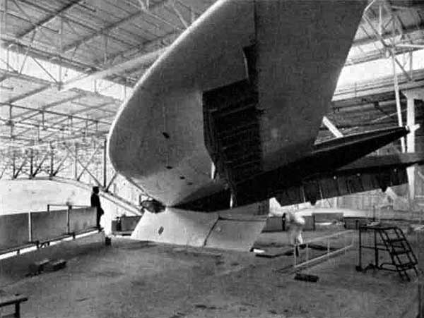
The erection of the steel spans posed a problem not often met. The approach spans would not be built in time to give access so the spans had to be built in isolation in the middle of the bay and 60 metres above the water. The solution was to assemble complete girder spans at ground level, transport them to the piers and jack them up into final position.
The details of the design were modified where necessary by RDL(C) Ltd. to suit British shop fabrication practice, transport to Brazil and the erection scheme.

The erection scheme required the centre 176 metres of the centre span to be built first and launched into the water. This section would then be used as a pontoon. The Niteroi side span would then be built together with a 62 metre section of the main span and the 30 metre cantilever at the opposite end. This 292 metre length of bridge would then be separated along its longitudinal centre line and one half carried by the pontoon to one side of the base of the Niteroi piers.
The second half of the side span would be similarly transported by the pontoon to the other side of the piers. The half girders rested on special girders built around the base of each pier. Specially designed jacking gear would lift the side spans to the tops of the piers where the two halves would be drawn together and the longitudinal centre joint remade.
The Rio side span would be similarly built, transported to the pier bases, jacked to the top of the piers drawn together and rejoined along its centre line.
The pontoon unit would then be lifted from the water on links hanging from the 62 metre cantilevers in the main span and the final joints made.
The 44 metre suspended spans would be built, launched into the water and lifted into place using conventional winches blocks and tackle.
The Island of Caju near Niteroi was chosen for the working area for assembly. The Island had a straight quay which was extended with a steel piled jetty to make it long enough on which to build the 292 metre maximum length of bridge. The Island was also suitable for the very complicated water borne operations.
Three 35 ton derricks were set on gabbards which travelled parallel to the quay to build the box girders. Three other 32 ton derricks serviced the rest of the working areas behind the main assembly area. A big advantage of using the Island was that the ship carrying the fabricated steel from the U.K. could actually tie up to one corner of the quay in a position where one of the assembly derricks could lift pieces directly from the hold.
Two steel piled concrete jetties were built out from the quay 192 metres apart so that when completed on the quayside the bridge sections could be moved out along them over the water. The more heavily loaded jetty had to carry a load of 1400 tons spread over a length of about 7 metres at any position in its length.
The first permanent steelwork to be assembled on the Island quayside was 176 metres from the centre of the main span. This consisted of the complete cross section of the twin box structure. Lower flange panels were laid down first and the longitudinal and transverse plate welds made. The internal framing was then erected which in turn supported the web panels which were pre-assembled to the complete depth of web.
The web panels were then welded to the lower flanges. Next the orthotropic deck sections were positioned, the longitudinal butt joints made between adjacent deck sections and the overhead fillet welds made to the webs. Then, after adjusting the sections for shop camber the transverse butt joint was made in the top deck plate. Only then were the vertical butt welds made between the adjacent web sections. Finally all the longitudinal web and bottom flange stiffener joints were welded also the joints in the longitudinal trough stiffeners of the deck.
The B. S. C. Research Laboratory on Teesside and the Welding Institute cooperated with the contractors in establishing the welding procedures and parameters.
This 116 metre length of bridge was destined to be used as a pontoon. Each box was divided into watertight compartments with plated diaphragms. Special stiffening was also added to enable the pontoon to support the concentrated loads when carrying the side spans. Additional cross bracing frames were added between the two boxes.
The effective length of the pontoon was increased to 192 metres by bracing frames to match the spacing of the jetties projecting from the quay.

The section when complete was jacked up from its assembly stillage. This operation saw the first use of the specially designed jacking gear to lift the 3,800 tonnes. The jacking columns and jacks were incorporated in the braced extensions at the ends of the pontoon which in turn were carried by sledges.
The 3,800 ton section was moved sideways past the edge of the quay and out over the water. It was desirable not to place the pontoon in the water until the latest possible time as the period of immersion would have an effect on the amount of marine growth it would collect.
When the time did come to put the pontoon section in the water it was first painted with a strong anti-fouling paint over the immersed areas. It was lowered into the water by the special jacks jacking themselves and the pontoon down the jacking columns. Once in the water the braced structures and jacks were removed from each end. The pontoon was equipped with six diesel driven pumps for pumping ballast in or out of any of the twelve compartments. Four 10 ton diesel winches and four hand winches were fixed to the deck for handling moorings.
To carry the bridge sections two heavy temporary steel trestles in the form of an ‘X’ were erected on the deck. A central command position was set up linked to all key points by telephone.
Before the centre piece had been moved off the camber blocks the assembly derricks had begun to build the first of the side spans at two positions beyond each end of the centre section. The side span consisted of the 200 metre side span proper, together with 62 metres of the centre span and the 30 metre cantilever fro1n the approach span. This 292 metre length of bridge stretched the whole length of the island face and temporary extension. The actual length was monitored during building so that when completed the span would be correct to fit the piers.
The side span was built as a complete twin box cross section. When completed the side span was separated along its centre line into two single box structures. The first half of the side span nearest the water was jacked up at points opposite the concrete jetties, the longitudinal camber changing dramatically by 70cm. The second half span was jacked up from the camber blocks. In this position the longitudinal and vertical alignment of the two sections could be compared. There was a slight bow of 5cm in the total length of 292m and the vertical deflections were practically identical.
The two half side spans were then moved out onto the concrete jetties on sledges. The total weight moved being 4,500 tons. Once clear of the building berth the Niteroi side pan was left until required to be floated out on the pontoon .
The assembly of the second or Rio side span was then commenced on the camber blocks and was in fact structurally completed before the piers out in the bay were ready to receive the first side span. Thus the whole of the steel spans totally 848 metres of bridge were assembled at ground level at the island working site ready to be taken out to the piers in the bay.
When the first pair of piers was available they were prepared to receive the Niteroi side span. Temporary steel box girders were built around the twin concrete shafts at pile cap level. These ring girders were jacking up the piers placing steel jacking columns on the end faces of each pier above themselves as they went. The ring girders were then jacked up the columns they had just placed. The special 450 ton jacks were positioned below the ring girders and moved up the columns carrying the ring girders as the jacking proceeded like a ‘monkey on a stick’. There were twin columns each with a pair of jacks on each face of the main channel pier and single columns and twin jacks on each face of the side pier. 12 jacks with a total lifting capacity of 5,400 tons. The ring girders projected beyond the faces of the pier shafts as cantilevers on which the half side spans could be landed.
Preparations were made for the first of the pick-a-back operations. The first half of the Niteroi side span was now moved to the end of the concrete jetties. All the floating operations were carried out at night, starting early evening and finishing early morning, when the bay always seemed to be at its calmest.
The pontoon alongside the side span was flooded with 6,000 tons of ballast water and warped beneath the sidespan unit on the jetties. Once in position the ballast water was pumped out of the pontoon causing the side span above it to be lifted clear of the concrete jetties. The camber of the side span was dramatically changed again from a sag of 60cm to a hog of 50cm.
The side span was supported on the two temporary trestles on the pontoon. These trestles were designed to accommodate the relatively large angular and translational movements between the side span and the pontoon due to stress changes and the effects of temperature variations.
Five tugs took charge of the pontoon carrying the half side span and towed it through a difficult navigation channel and out into the bay to be moored to .one of the Brazilian navy buoys. This strange craft, displacing about 6,000 tons was larger than an aircraft carrier. A crew was left aboard to get things ready for the next operation and to warn off any errant flyers. The side span rode out rough • weather at the buoy for a few days.
The operation of landing this half of the side span at the piers was commenced in the late afternoon. The pontoon unit carrying the half side span was floated in· between the pier bases on the North side. The final positioning was carried out by moorings and hauling ropes attached to the piers. By pumping ballast water into the pontoon and the effect of the falling tide the span was lowered until contact was made with the· ends of the ring girders around the piers. The girder moved vertically in the swell until firm contact was established. The addition of further ballast water transferred the total weight of 2250 tons of the side span to the ring girders. Yet more ballast was added to free the pontoon and the trestles from the side span so that it could return to the Island.
The profile of the span was back to a sagging condition. The landing of the sidespan on the ring girders was a complicated operation requiring careful co-ordination in all its facets. It was also very dependent on the weather, the tides and the water conditions.
The span was supported on the ring girders by a system of hydraulically linked jacks and packs which allowed the large movements due to stress changes during the landing of the span to take place. Also substantial movements occurred as the sun beat upon the top flange during the day and the girder cooled off during the night.
At Caju Island the second half of the Niteroi side span had been moved out to the ends of the jetties. The pontoon picked up this side span and took it to the South side of the first two piers. Here it was landed at night on the opposite ends of the ring girders and the pontoon returned to the Island.
The two half side spans supported by the ring girders were then jacked up the two piers by the jacks below the ring girders. The total weight actually lifted was 5,275 tons and was the second heaviest bridge jacking operation in the world. The height lifted was 52½ metres and was accomplished in 3½ days. All operations were controlled by telephone ‘walkie talkie’ and coloured light systems from a control cabin at the centre of the side span. This complicated and delicate operation was carried out by a well trained team of British and Brazilian staff, the latter speaking no English. The British staff translated into Portuguese for the Brazilian staff.
The two halves of the span now at the top of the piers were then moved laterally towards each other to be landed on the pier bearings. This was the moment of truth to see how bad or how good the centre longitudinal joint lined up. The joint exceeded all expectations. The difference in level at centre span between the two halves was less than 5mm and the horizontal gap between the deck plates was such that welding could start immediately.
The ring girders were jacked down the piers removing the jacking columns as they went all to be reassembled on the second pair of piers.
The pontoon repeated its pick-a-back operation twice more carrying the two halves of the Rio side span from the Island jetties to be landed on the ring girders at the bases of the piers. The girders were jacked up the piers, moved across at the top and landed on their bearings. The longitudinal joint fitted like a seam in a carpet.
While this work had been going on the 44 metre suspended spans were built one at a time on a disused slipway on the Island which was refettled for the purpose. The complete cross section was built and launched into the water. The Niteroi 44 metre span was hoisted one half at a time weighing 250 tonnes with tackles to fit between the steel and concrete opposing cantilevers.
The 176 metre centre section of the main span had to be prepared now for its own erection. It was cleared of the temporary trestles, pumps, most of the bollards and fairleads. Four of the 450 ton climbing jacks· were fitted at each end of the pontoon.
In the main 300 metre span there was a 62 metre cantilever projecting into the span from each side span. The special jacking columns from the piers were hung from the ends of these cantilevers down to water level.
The centre section was towed out into the bay and moored beneath the gap it was to fill. Another night operation was planned to lift the unit from the water in order to have the calmest conditions in the bay.
The initial connections had to be made between the suspended jacking columns and the jacks fixed in the unit which rolled and pitched in the swell. With the connections made the jacks climbed three steps totalling 4½ metres up the jacking columns. During the third step the pontoon bottom came clear leaving its watery support after a year afloat. The full weight of 3,420 tons was now hanging on the main span cantilevers. This transference of load dramatically changed again the profile of the side spans from a sag of 60cm to a camber of 1.1 metres. The stresses in the centre unit were also changed considerably. Thus all highly stressed parts of this welded structure have been stress relieved by the process of erection. The moorings were discarded and jacking in earnest began. The hydraulic circuitry was as used for the jacking of the side spans. The control was at the centre of the span. An elaborate but necessary system of warning buzzers and flashing lights was used to draw attention to any untoward happenings. Standby hydraulic pumps and reserves of hydraulic oil were also provided if needed.
The jacks had to climb a total height of 67 metres represented by 44 jacking steps. The jacking continued by day and the structure was monitored by night until the unit was two thirds of the way to the top. Then a switch was made to jacking at night and watching by day to avoid the worst complications of the effects of the very high daytime temperatures in the sun; and so the last steps were climbed at night. The entry of the piece into the gap was good and the permanent lower flange covers were immediately erected and bolted up. For speed of connection these two transverse joints in the girder were bolted.
As the joints were not at the points of contraflexure of the main span the top flange joint still had a gap of 5cm and the webs corresponding tapering gaps with the lower flange bolted up. The top flange gap was closed by a force of 1,000 tons applied to the flange by groups of prestressing bars attached to anchorage plates welded each side of the joint to pull it together. The flange and web covers were placed and bolted up. Not until the web joints had been made could the main jacks be released from their load for removal. The jacking column strings were then dismantled.

The 760 metre continuous length of the bridge was then complete. There retnained only the Rio 44 metre suspended span. This was erected in two halves using tackle.
The precast concrete parapets and central median barrier were erected. The epoxy asphalt surfacing 6cm thick was laid by machine.
The bridge which includes the 300 metre longest girder span in the world was inaugurated by the President of Brazil on March 4th 1974 and opened to traffic the following day.