
Projects and Features
Fire boundary conditions and the distribution of unprotected areas
The so-called “fire boundary condition” is an important consideration for designers of single-storey buildings. Max Cooper of the SCI offers some thoughts on the use of Approved Document B Table 13.1 and its suitability for use with large buildings.
Where a building is situated close to a site boundary, its external walls must provide fire resistance to limit the risk of fire spreading to neighbouring property. Approved Document B sets out simplified rules for determining the allowable proportion of wall which is not required to provide fire resistance.
There is scope for confusion in the Approved Document B guidance regarding the allowable percentage of “unprotected areas”, and in particular the relationship between the simplified table in Approved Document B (Table 13.1) and the guidance it was preceded by, and broadly derived from, BRE Report 187.
Background
The Building Regulations for England and Wales state that a building must be constructed so that “its stability will be maintained for a reasonable period” in the event of fire, and external walls must offer “adequate resistance to the spread of fire” between buildings. It is the second of these requirements regarding the spread of fire, that concerns this article. Though not the only route, compliance with Approved Document B is the most common way to demonstrate compliance with the Building Regulations.
Radiation is the principal mechanism of the spread of fire between buildings, and the external walls of a building serve as a barrier to this radiation. Approved Document B requires that walls close to a site boundary have fire resistance (defined as stability, integrity and insulation in the presence of a fire). Parts of the wall that do not meet this standard, such as windows, doors, or non-fire-rated cladding, are termed “unprotected areas” and are also commonly referred to as “openings”.
Determining the suitable boundary distance
The peak radiation intensity emitted during a fire depends on the size and distribution of unprotected areas across a façade. The larger an unprotected area, the greater the radiation intensity, thus requiring a large distance to the site boundary to ensure fire does not spread. As a general approach, Approved Document B refers to BRE Report 187, External fire spread: building separation and boundary distances, which provides a physical model and associated calculation method for determining acceptable boundary distances based on these parameters. Each unprotected area may be considered individually, or as a collection across a building façade within an “enclosing rectangle”, for which an approach based on the average unprotected percentage is permitted.
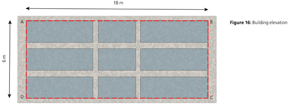
A building with internal fire compartments is treated by assessing each compartment independently, essentially as separate buildings. This may benefit the designer by reducing the width and height of the enclosing rectangle.
It is also possible to use the same calculation principles in reverse: for a given boundary distance, one can calculate the acceptable percentage of unprotected area within an enclosing rectangle. The greater the distance, the more unprotected area is permitted. At a sufficient distance, the entire elevation may be unprotected.
It is the second of these approaches that is adopted in the simplified tables provided in Approved Document B.
Approved Document B Table 13.1
Approved Document B provides two simple methods for calculating the acceptable percentage of unprotected area based on the distance to the relevant boundary.
Method 1 applies only to small buildings not exceeding three storeys or 24m in length so is not relevant to most industrial buildings.
Method 2 is intended for buildings or compartments of any use for which Method 1 is not appropriate, provided the building does not exceed 10 m in height. It is clear that any building taller than 10m must follow the guidance in BRE 187 directly. Method 2 states “Each side of the building should meet the limits in Table 13.1.” It is worth noting that the title of Table 13.1 still refers to “Permitted unprotected areas in small buildings or compartments” yet provides no definition of what constitutes a “small” building in this context other than the 10 m height limit.
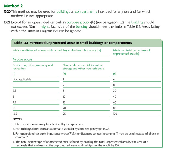
Table 13.1 lists the maximum permitted percentage of unprotected area for a given boundary distance, with separate columns for different purpose groups. For industrial buildings, the permitted unprotected percentage ranges from 4% at 1m boundary distance up to 100% at 25m. Clause 13.21 of Approved Document B requires that “each side of the building should meet the limits in Table 13.1”. Read casually, this could be taken to mean that the unprotected percentage is calculated over the full area of the building side.
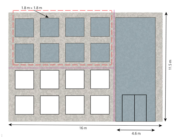
Note 4 to Table 13.1 states: “the total percentage of unprotected area is found by dividing the total unprotected area by the area of a rectangle that encloses all the unprotected areas, and multiplying the result by 100”. Therefore, the enclosing rectangle is not necessarily the same as the entire building side, and for a façade with openings concentrated in one area, the enclosing rectangle may be considerably smaller, resulting in a higher percentage of unprotected area. To those familiar with BRE 187, this distinction may be clear, though users who are not familiar with the underlying concept may be forgiven for overlooking it.
A further omission in the Approved Document B method is the assumption in BRE 187 that “unprotected areas are uniformly distributed over the enclosing rectangle”. BRE 187 notes that if the unprotected areas are not uniformly distributed, “there may be hot spots which should be treated independently”. Again, for those familiar with the basis for the external wall requirements, this will make intuitive sense – a concentrated area of openings will result in a high level of radiation in the event of a fire and require a corresponding large distance to the relevant boundary. This fact would be unchanged if the opening was part of a large protected façade.
A brief history of “Table 13.1”
Up until the 1985 edition of Approved Document B, the guidance reproduced the BRE 187 method and tables directly. The width of the enclosing rectangle was an important parameter: a wider opening required a greater boundary distance, even for the same percentage of unprotected area.
In the 1992 edition of Approved Document B, the simplified Method 2 was introduced. The width of the enclosing rectangle no longer features as an input parameter, and rather than extracting numbers of the earlier BRE 187 tables, it appears to depart entirely from the analytical approach; inspection of Table 13.1 reveals that the allowable unprotected percentage for industrial use is simply four times the boundary distance (in metres). For residential, the multiple happens to be eight. This relationship clearly has no direct basis in the radiation calculations.
There is no question that the BRE method can be complex, particularly when applied outside of the textbook worked examples; for small and regularly compartmentalised buildings this simplification is pragmatic and will produce acceptable results. However, for large uncompartmentalised buildings such as industrial sheds the distinction between the simplified Approved Document B method and the full BRE 187 calculation becomes significant. It is understandable that designers would want to rely solely on the Approved Document, but for large buildings it is recommended that the BRE 187 method be used instead.
Examples
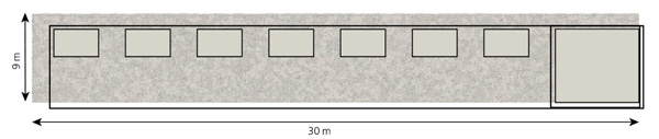
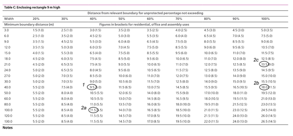
To demonstrate the use of the BRE 187 method, first consider a building 40m long and 9m high, classified as industrial use with the long elevation situated 10m from the relevant boundary.
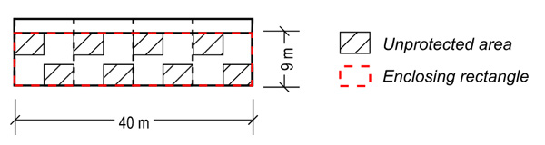
From Approved Document B Table 13.1, this building side may be 40% unprotected – equivalent to an unprotected area of 144m² on a 360 m² façade. When measured against the requirements of BRE 187 Table C (over page), we see that the minimum boundary distance for a 40m wide, 40% unprotected area is 9.5m, therefore less than the 10m required by Approved Document B. So far, so good.
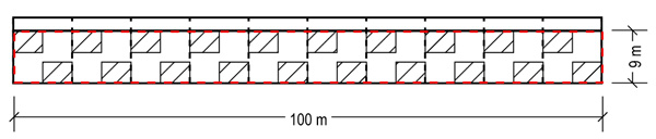
Now consider an otherwise identical building 100m long. Again, from Approved Document B Table 13.1, this building side may be 40% unprotected – equivalent to an unprotected area of 360m² on a 900m² façade.
If that 360m² is evenly distributed across the full length of the elevation, the enclosing rectangle would be 100m wide with unprotected area of 40%. BRE 187 would now require a distance of 11.5m to the boundary. A moderate increase, and slightly greater than the 10 m required by Approved Document B.
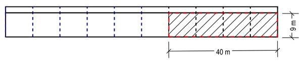
If, however, the same unprotected area is grouped at one end, a 40m wide section would be entirely unprotected. A 40m wide, 100% unprotected area, assessed using BRE 187 Table C would require a minimum boundary distance of 18m, far greater than 10m, and clearly demonstrating the importance of Note 4 requiring the use of an enclosing rectangle rather than the entire building side.
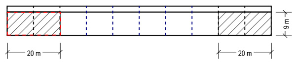
Alternatively, consider a perhaps unlikely arrangement of two 20m × 9m unprotected areas. This time the arrangement of openings meets the requirements of Table 13.1, Note 4 as a single 100m rectangle would be required to enclose both areas. Considered as a whole, the minimum acceptable boundary distance would be the same as that of Example 2a, however, considered as individual openings (i.e. 20m wide, 100% unprotected), BRE 187 Table C would require a minimum boundary distance of 13.5m, 35% greater than the 10m required by Approved Document B.
Clause 2.2 of P313
The query that prompted the writing of this article concerns the application of Clause 2.2 of SCI Publication 313. Clause 2.2 states:
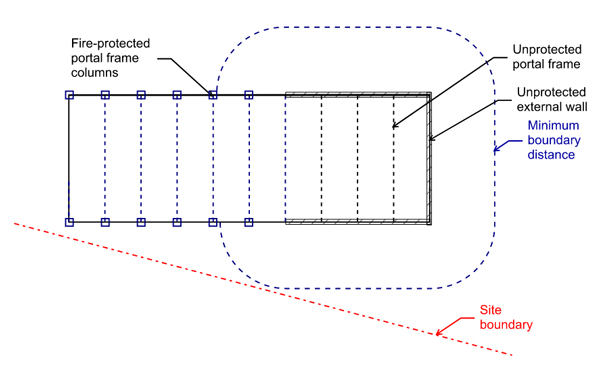
“These recommendations apply to columns supporting protected areas of external walls. Columns supporting protected areas will require fire protection up to eaves level, regardless of the extent of the protected area. Therefore, when less than 100% of the wall is required to have fire resistance it is preferable to arrange the protected area so that it covers as few columns as possible thereby minimising the requirements for fire protection and moment resisting bases.”
Read in isolation, this advice encourages the designer to consolidate the protected area into as few bays as possible, and, by extension, concentrate the unprotected area over the rest of the building side. But as the preceding example demonstrates, it is unlikely to be possible to arrange the unprotected areas in such a concentrated manner and still satisfy an assessment to BRE 187.
Where the relevant boundary is skewed relative to the building, it would perhaps be possible, but the structural engineer would need to demonstrate that unprotected structural elements would not compromise the stability of the protected elements. In practice, this means demonstrating that the collapse of unprotected columns and rafters in the fire-affected zone would not pull down the protected columns and the wall they support. In the past, a designer may not have felt it necessary to provide formal justification for this; but in the post-Grenfell regulatory atmosphere, that is unlikely to remain the case, where designers are increasingly expected to demonstrate the robustness of their fire design through analysis rather than precedent alone.
Conclusions
The simplified table in Approved Document B Table 13.1 is a useful tool for small buildings, but it should not be applied uncritically to large uncompartmentalised buildings. For large building, BRE 187 should be used to verify that the proposed arrangement of unprotected areas is acceptable.
The intent of the guidance in P313 to minimise the number of columns requiring fire protection by concentrating the protected area is understandable, but designers should recognise that the resulting concentration of unprotected area may require a greater boundary distance than Table 13.1 from Approved Document B would suggest.

