Projects and Features
Digitally enhanced
Software for steelwork designers becomes increasingly sophisticated. Whether the aim is to automate detailed design of individual components, or create a model of an entire structure, software providers continue to make great strides. In the first part of a software round-up, New Steel Construction looks at some of the latest releases for designing cellular beams and for 3D modelling.
Added floor options for ASB software

Latest version of Slimdek ASB includes data for design with precast floors

BDES provides rapid designs for composite floors

Composite floor designed using BDES
Corus’s latest version of its free Slimdek ASB asymmetrical beam software is helping the structural steelwork industry compete in both the commercial and residential markets.
Asymmetrical beams allow the service zone to be kept to a minimum while still allowing easy access to services which typically have a design life of about 15 years to the building’s 60.
ASBs rely on the floor to restrain the top flange from buckling and until the latest release, the software only covered design with deep steel deck floors.
The new version 4.1 allows ASBs to be designed with precast units from all the major manufacturers. “The advantages of precast units is that you’re unlikely to have to prop, and you can get above a 9m x 9m grid,” says the Steel Construction Institute’s Senior Manager for Information Technology John Moran. It also allows highly unequal spans to be modelled.
Also recently issued is a new version of the composite beam design program BDES. There was surprise at how much this was missed when it was left off the last free Corus CD in 2003. Evidently, though, its ability to produce rapid designs for composite and non-composite beams is valued by engineers. It allows primary and secondary beams to be modelled, with a concrete slab or steel deck floor acting compositely with the beam. BDES permits the modelling of a wide variety of load configurations together with flexible layout of beam openings.
Changes in the new version 7.3 include analysis to the provisional Eurocodes, ENV 1993 and ENV 1994, improved capabilities to deal with a wider range of web openings, and the inclusion of Hilti shear connectors as well as welded studs.
Both the new offerings have been brought into the SCI’s new quality management regime. “What users see is software that ‘knows’ when it needs to be updated,” says Mr Moran. In addition, behind the scenes is a quality audit trail for all software development which is being offered for ISO 9001 accreditation.”
Corus software is available as free downloads from www.corusconstruction.com/ page_9033.htm
New look, new links
AceCad has introduced a range of improvements to the latest release of its StruCad 3D modelling package, version 11, which came out last month.
The most obvious is a complete update of the user interface so that the package now has the look of a modern Windows application. Standard Windows toolbars are employed, which can be customised to suit the individual user. Existing users who are happy with the old interface can continue to use that instead, though, if they prefer.

Solid modelling package Strucad v.11 gets an improved interface and includes automatic connectability, cold-rolled section design and an estimating module

Solid modelling package Strucad v.11 automatic connectability

Solid modelling package Strucad v.11 cold-rolled section design screen
There are a number of other improvements. Among them is an increase in the maximum number of members that a model can include. Previously this was limited to 10,000, which meant that very large projects had to split into separate chunks. In version 11, modelling limits have been virtually removed. Memory is allocated dynamically so that only the memory necessary for the number of items is used.
There is now the ability to include references to external drawings in 2D or 3D, in SPF or DXF file formats. This is useful for bringing in architectural models or when using a combination of materials.
AceCad’s Charles Wilby says that the limit to the big productivity gains that can be achieved from CAD, purely through automation of the drawing process and by adding new features, is being reached. “The hold-ups these days are in information flow between companies and between departments of the same company.”
The company is thus concentrating its efforts on improving StruCad’s ability to link to other packages, to check information and communicate; and on developing StruM.I.S, which provides a complete management package of the whole fabrication process from estimating to production control.
“The big gains in future will come from management of information systems,” he says.
Ability to import and export via StruCad’s Analysis and Design option or StruCad Engineer has been improved, with support for the CIS2 neutral file format (designed to become a standard for date exchange between different software packages). There is also a direct link to the widely-used analysis package Staad.
AceCad has worked closely with manufacturers of cold-rolled sections to improve its ability to model cold-rolled purlins, including a new side rail support system.
Links to StruM.I.S have been enhanced, and an estimating module has been built into Strucad which can calculate not only the price of the steelwork, but also fabrication, painting, transport and erection costs.
Wilby stresses: “As opposed to our competitors, a significant difference we have is that we concentrate on the steel market and the steel industry’s needs solely.”
One model for all
Talk to steelwork detailers and you’ll soon find that Xsteel is one of the most popular steelwork modelling and detailing packages.
These days Xsteel is better known as Tekla Structures Steel, or more accurately as one configuration of the Tekla Structures Suite, which now covers a much broader range of capabilities. Tekla (UK) Managing Director Chris Moor says that the software has evolved into a completely integrated structural model that effectively forms a building information model for structural engineering projects.

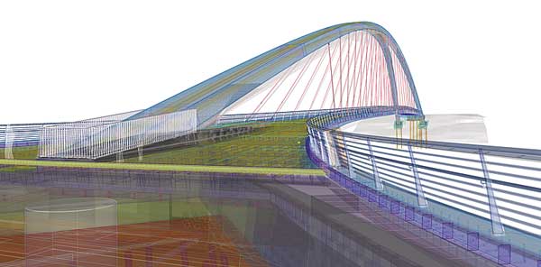
Tekla Structures was used to model the complex roof of the Welsh Assembly

Welsh Assembly used Tekla Structures to model the complex roof
BIM systems are the Holy Grail of construction software developers. A BIM is a single 3D model covering the entire design process from concept to detailing, fabrication and construction, containing all the geometric, structural and project information, and allowing multiple users to work on the model simultaneously. In manufacturing, automotive and aerospace companies have for some time been using single computer models, but these industries have supply chains dominated by a few powerful companies such as Ford or Boeing who are able to impose standards on their suppliers.
In construction, a more fragmented situation means a single BIM containing all architectural, structural and services information is still a few years away, according to Moor. However, argues Moor, a structural BIM, containing all the information an engineer, detailer, fabricator or project manager needs (including drawing and report production) is provided by Tekla Structures now.
As well as providing an integrated model for the structural engineer, the software will readily link to other programs such as Autodesk and Bentley, commonly used to model piping and M&E details.
“That’s our concept,” says Moor. “It allows everyone to talk to each other and everything in the project is coordinated.”
Though the main customer base is steel fabricators, detailers and structural engineers, Tekla has been successful in selling specific Tekla Structure configurations. “They appreciate the ability to collaborate with the steel frame suppliers and exchange models, because clashes between the frame and precast flooring or cladding are a common source of trouble.”