
Projects and Features
Beyond assumptions – why structural engineers should specify critical temperatures
Max Cooper of the SCI discusses the specification of fire protection for structural steelwork and argues that while greater collaboration between all parties is required, it is the structural engineer who is best placed to produce the information needed to allow others to provide a precise, cost-effective and safe specification.
The specification of fire protection for structural steelwork is, in many cases, not done well. On a typical steel-framed building, the structural engineer designs the frame and specifies the elements that are to be protected for a given fire resistance period. What that protection is, most commonly an an intumescent coating that expands when heated to form an insulating char (Figure 1), and more importantly, the required specification (i.e. coating product and thickness), is left to others. Those “others” may be a specialist fire protection contractor or a coating manufacturer’s technical department. Whatever the specifics of the arrangement, the structural engineer’s involvement in fire protection often ends with a few notes on the general arrangement drawings.
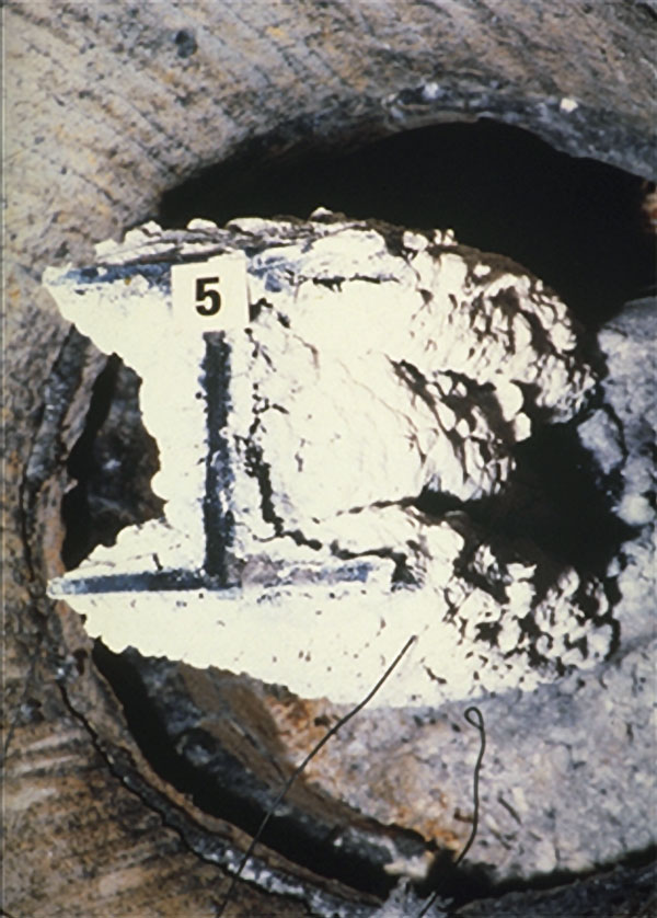
This arrangement is understandable and has worked, after a fashion, for many years. But the result is a fire protection specification that is frequently overly conservative and costly, and in certain circumstances may be inadequate.
To determine the correct thickness of intumescent coating for a given fire resistance period, the specifier needs to know three things: the section factor, the exposure condition, and the critical temperature of the element. The section factor is the ratio of the heated perimeter of the section to its cross-sectional area, defined as Am/V in the Eurocodes (though often still referred to by its BS 5950 notation, Hp/A), and can be readily found for a given steel section size in publications such as the SCI ‘Blue Book’1. The exposure condition, i.e. whether the element is exposed to fire on three sides (e.g. a beam supporting a concrete floor slab) or four (e.g. a column), should be fairly obvious. The critical temperature is not.
What is the critical temperature and why is it so important?
The critical temperature (ϑa,cr) is the temperature at which a steel member’s structural resistance, calculated using the reduced yield strength and reduced stiffness of steel at elevated temperatures, is equal to the applied design load in the fire condition. As shown in Figure 2, the effective yield strength of carbon steel begins to reduce above temperatures of 400°C, whilst its elastic stiffness starts to reduce above temperatures of 100°C. The lower the critical temperature, the greater the thickness of fire protection required to insulate the element.
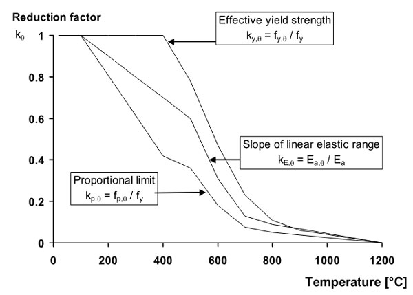
There are various methods of determining the critical temperature of an element, requiring knowledge of the structural design to a greater or lesser extent. One common approach is to use the default values tabulated in the ASFP ‘Yellow Book’. Both the 5th edition2 and the 6th edition3 remain in circulation, so it is worth discussing the assumptions used in the development of both.
The 5th edition of the Yellow Book provides a flowchart directing the user to various tables of critical temperatures depending on how much information is available. If the type of loading is not provided, the flowchart directs the user to default critical temperatures of 500°C for columns and 550°C for beams. Where the floor occupancy category is known, Table 16 of the 5th edition provides critical temperatures for specific member types (such as composite or non-composite beams supporting floor slabs, and UC or hollow section columns) across different building uses (e.g. office or storage).
These Table 16 values rely on pre-determined values of ηfi, the ratio of the fire design load to the ambient ultimate limit state (ULS) design load. The ratio ηfi can be derived from the ratio of variable to permanent actions; common assumptions might be 1:1 for offices and 2:1 for storage. Crucially, in using Table 16 and considering only ηfi, the specifier is implicitly assuming that the member is 100% utilised in the ambient ULS design. While this may not be unreasonable for some column designs, it is typically highly conservative for beams, where serviceability deflection limits commonly govern ambient design and ULS strength utilisations might be closer to 70%.
The 6th edition of the Yellow Book made substantial simplifications by replacing the previous occupancy-based tables with a single table of default critical temperatures: 580°C for 3-sided beams supporting slabs, 550°C for 4-sided beams and tension members, and 500°C for compression members of any shape. These defaults are based on a single limiting degree of utilisation in the fire condition of μ0 ≤ 0.6 across all scenarios, removing the need for the specifier to know the floor usage.
It should be clear that the underlying assumptions of this simplified approach bring both economic and safety compromises:
- For typical office floors where ηfi is around 0.6 and beams may have significant spare ambient capacity due to being deflection-governed, assuming μ0 = 0.6 is overly conservative.
- For storage occupancies, ηfi will be greater than 0.6. Unless a beam supporting a storage floor has sufficient reserve capacity at ambient temperature to bring μ0 below 0.6, the 6th edition default critical temperatures are unconservative.
- Neither the 5th nor the 6th edition clarifies that their tabulated values for beams, including “4-sided beams not supporting concrete slabs” in Table 7 of the 6th edition, apply strictly to laterally restrained beams. Unrestrained beams require separate evaluation.
The UK National Annex and its pitfalls
A more precise measure of how hard an element is working in fire is its degree of utilisation, μ0, which represents the ratio of the fire design load to the member’s structural resistance at ambient temperature. In most common design cases where the loading arrangement is the same at ambient ULS and in fire, μ0 is the product of ηfi and the ambient ULS strength utilisation. Where μ0 is known, the specifier can use Table NA.1 in the UK National Annex to BS EN 1993-1-24. For beams with realistic ambient utilisations, this yields a higher critical temperature than the ASFP tables, allowing a reduced thickness of fire protection.
Some caution is required when using Table NA.1 for compression members. The tabulated column temperatures assume grade S355 steel and an ambient buckling curve ‘c’ imperfection factor of α = 0.49, appropriate for S355 UC sections buckling about their minor axis. For compression members with an ambient imperfection factor lower than 0.49 (such as hot-finished hollow sections, S460 UCs, or UBs), the tabulated values can be unconservative unless the designer can assume a reduced buckling length in the fire design condition as is permitted in braced multi-storey frames. Designers should refer to Advisory Desk note AD 5465 for a full explanation of these limitations and replacement values. It should be noted that these points are also relevant to the critical temperatures provided in the ASFP tables.
Why the structural engineer is best placed to specify critical temperatures
What should now be clear is that the more design information available to the protection specifier, the more accurate and safe the specification can be.
Even the most competent fire protection specialist cannot determine this information unless it is given to them. While a specialist might have access to loading plans showing superimposed dead and imposed loads, calculating ηfi would still require the specialist to estimate the self-weight of the structure and floor slabs – one suspects they rarely would, and even less often be willing to take responsibility for these calculations. Unless informed by the designer, they cannot know a member’s ambient ULS utilisation or its effective buckling length used in design. Without this information, they are obliged to fall back on conservative (or occasionally flawed) assumptions. Conversely, if the structural engineer calculates and states the critical temperature, it encapsulates all of these structural parameters into a single figure that the specifier can use directly.
There are also situations where the fire limit state regime bears no resemblance to the ambient ULS design. A prime example of this is a single-storey portal frame designed in accordance with SCI P3136 for the so-called ‘boundary condition’, where the unprotected rafters are assumed to collapse in a fire. This induces a substantial overturning moment at the base of the protected column that far exceeds ambient ULS demands, resulting in high utilisation in the fire condition to the extent that it may even govern the column size. This will result in a very low critical temperature and a significant fire protection requirement. Who but the structural engineer of that column could possibly know this?
At the other end of the spectrum, the impact of a more precise estimate of the critical temperature on intumescent coating thickness can lead to substantial savings. Consider a protected composite beam supporting a composite slab, whose fire utilisation μ0 varies according to the ratio of variable to permanent loads and ambient design utilisation. From Table NA.1 of the UK NA to BS EN 1993-1-2, at a utilisation of μ0 = 0.65 (corresponding to a beam at near 100% ambient utilisation) the critical temperature is 573°C. At a more typical utilisation of μ0 = 0.40 (corresponding to a beam supporting office loading with ~70% ambient utilisation), the critical temperature increases to 654°C. Between 573°C and 654°C, the required dry film thickness (DFT) of a typical intumescent coating increases by roughly a third – which might be the difference between a single coat and a two-coat system, with implications for paint volume, labour and curing time in the fabrication shop.
Joining up the dots?
It would benefit the entire sector if structural fire design were no longer treated as a separate discipline divorced from normal frame design, despite how it may be typically framed in contractual scopes. Fundamentally, fire design of steelwork is simply the verification of structural elements at elevated temperatures using modified material properties and imperfection factors, and reduced design actions – all of which are set out in BS EN 1993-1-27 and BS EN 19908. Extensive worked examples demonstrating these checks have been published in New Steel Construction by the SCI’s David Brown, covering restrained composite and non-composite beams9, columns in compression10, laterally unrestrained beams11, and members subject to combined axial load and bending12. If there is any inconvenience or challenge involved, it is the iteration required to find the temperature at which the resistance exactly equals demand – though this is a task that can be readily automated in a spreadsheet or design software. Documenting the output critical temperatures is as straightforward as adding a column to a beam or column schedule.
So why has this not been done in the past? Structural engineers are understandably reluctant to take on responsibility and additional work for scope they have not historically been paid to deliver, and unless the scope is explicitly requested then this is unlikely to change. There can also be caution around how fire-related calculations are covered by PI insurance – some insurers have historically excluded this work from their policies. Until critical temperatures are required and costed for as a standard Stage 4 deliverable from the structural engineer, those who include them voluntarily may feel at a commercial disadvantage.
Within the UK steel construction sector, there is already a clear demonstration of what can be achieved when structural design and fire protection are integrated. Suppliers of fabricated and cellular beams routinely redesign floor beams to optimise steel weight, and because they supply the intumescent coating as part of their package, they have a direct commercial incentive to calculate accurate critical temperatures. Furthermore, where the lightest possible steel section might demand a high DFT, they can evaluate whether a marginal increase in flange or web thickness reduces the coating thickness enough to provide a lower overall cost. This trade-off between steel tonnage and fire protection is only apparent because the party performing the structural design is also specifying and pricing the fire protection.
For the wider steel frame industry, this demonstrates the efficiencies possible when parties pull together. When the structural engineer, steelwork contractor and fire protection specialist operate in isolation and fail to communicate basic utilisation data, the resulting specification will rarely be optimal – and in certain cases may even be unconservative. The design processes are fully documented and well within the capabilities of any structural engineer. What is needed now is a willingness from engineers to include critical temperatures as a standard deliverable, and an understanding from clients and main contractors that the additional fee for this input will be recouped (and likely many times over) through more efficient fire protection specifications.
References
- SCI/BCSA, Steel building design: design data (SCI P363). Ascot: The Steel Construction Institute, 2015.
- Association for Specialist Fire Protection, Fire protection for structural steel in buildings, 5th ed., Vol. 1. Finchampstead: Association for Specialist Fire Protection, 2018.
- Association for Specialist Fire Protection, Fire protection for structural steel in buildings, 6th ed., Vol. 1. Coventry: Association for Specialist Fire Protection, 2025.
- British Standards Institution, NA to BS EN 1993-1-2:2005 UK National Annex to Eurocode 3: Design of steel structures – Part 1-2: General rules – Structural fire design. London: BSI, 2008
- Steel Construction Institute, ‘AD 546: Critical temperatures for compression members in the UK NA to BS EN 1993-1-2’, New Steel Construction, Vol. 33, No. 7 (July/August), p. 28, 2025. Available: https://www.newsteelconstruction.com/wp/ad-546-critical-temperatures-for-compression-members-in-the-uk-na-to-bs-en-1993-1-2/
- W.I. Simms and G.M. Newman, Single storey steel framed buildings in fire boundary conditions (SCI P313). Ascot: The Steel Construction Institute, 2002.
- British Standards Institution, BS EN 1993-1-2:2005 Eurocode 3: Design of steel structures – Part 1-2: General rules – Structural fire design. London: BSI, 2005.
- British Standards Institution, BS EN 1990:2002+A1:2005 Eurocode: Basis of structural design. London: BSI, 2005.
- D.G. Brown, ‘Fire protection of steelwork’, New Steel Construction, Vol. 32, No. 3 (March), pp. 24–27, 2024. Available: https://www.newsteelconstruction.com/wp/wp-content/uploads/2024/03/NSCMar2024-tech.pdf
- D.G. Brown, ‘Critical temperatures for fire design: Part 2 – Columns’, New Steel Construction, Vol. 32, No. 4 (April), pp. 24–27, 2024. Available: https://www.newsteelconstruction.com/wp/wp-content/uploads/2024/04/NSCApr2024-Tech.pdf
11 D.G. Brown, ‘Design at elevated temperatures – unrestrained beams’, New Steel Construction, Vol. 33, No. 4 (April), pp. 25–27, 2025. Available: https://www.newsteelconstruction.com/wp/wp-content/uploads/2025/04/NSCApril2025digi300a.pdf
12 D.G. Brown, ‘Members with axial load and moments – at elevated temperatures’, New Steel Construction, Vol. 33, No. 10 (November/December), 2025. Available: https://www.newsteelconstruction.com/wp/wp-content/uploads/2025/11/NSC-Nov2025-Tech2511.pdf