Technical
AD 309: Ductility of Fully Rigid Bolted Moment Connections
AD 305 deals with the requirements of bolted end-plate moment connections that are assumed for design to be fully rigid up to the Ultimate Limit State. However, since the publication of AD 305 the Advisory Desk has been asked whether these connections, with their thick end plates & flanges and bolt failure (mode 3) etc, have sufficient ductility or rotation capacity in various circumstances.
Moment connections are classified according to strength (moment resistance), rigidity (rotational stiffness) and ductility (rotation capacity). Figure 1.2 in Joints in Steel Construction: Moment Connections, (SCI-P-207) shows the various moment-rotation curves used in connection classification. Strength and rotational stiffness are the primary requirements for moment connections in steel structures analysed elastically. Likewise, strength and rotational stiffness are the primary requirements for moment connections in steel structures analysed plastically where the connections are not at the plastic hinge locations in the frame. The primary requirements for connections located at plastic hinges are rotation capacity and strength, which may be either full or partial strength. Strength, rigidity and ductility of connections are related to the deformation of the components in the connection.
Elastic Global Analysis
The fully rigid connections described in AD 305 have sufficient ductility when used in structures analysed elastically. Although not a primary requirement of elastic structural analysis, sufficient ductility is necessary in order to ensure that fracture does not occur in any component of the connection due to excessive deformation. SCI-P-207 stipulates minimum weld sizes or minimum design forces in order to utilize the ductility of the steelwork components instead of the welds. For bolts, SCI-P-207 stipulates a minimum number of threads in the stressed length of the bolt. This requirement is easily satisfied by the use of fully threaded non-preloaded bolts (Refer to AD 268 for the requirements of BS 5950-2: 2001 in regard to the number of threads in the stressed length of bolts). Moreover, in step 1C SCI-P-207 modifies the normal plastic bolt row force distribution to a linear distribution when both the beam end plate and column flange thicknesses are, in simple terms, greater than the bolt diameter in order to limit the deformation requirements of the bolts. When these requirements are satisfied, the connection will have sufficient ductility to ensure that fracture of its components will not occur in a steel structure analysed elastically.
Plastic Global Analysis
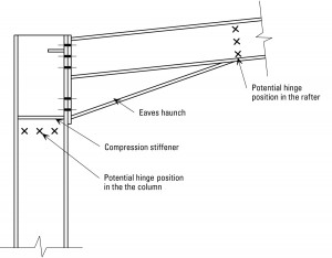
Traditional UK practice when designing single story portal frames plastically has been to ensure that a plastic hinge does not form within the haunch and clauses 5.2.3.8 and 5.3.5.1 in BS 5950-1: 2000 are examples of this practice. Figure 1 shows the two options for the location of the plastic hinge around the eaves when a plastic hinge does not form within the haunch.
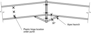
Figure 2 shows the normal location of the plastic hinge in the rafter close to the apex. In both cases the bolted moment connection is not at the plastic hinge location and therefore the fully rigid connections described in AD 305 may be used. However, industry practice is to use well proportioned connections designed for strength alone to be treated as rigid in the analysis of single story portal frames. Section 2.5 in SCI-P-207 permits this practice.
There is very little history in the UK of designing multi storey frames plastically and using bolted moment connections to form the beam to column connections. Therefore, it is not surprising that BS 5950-1: 2000 is silent on the issue of connections design for this type of frame where plastic hinges occur at the beam to column connection. However, other design codes offer the option of designing these connections for 1.2 times the plastic moment of resistance of the beam which implies that a small haunch will be required. The connection may then be designed as described in AD 305.When this approach is used the ductility of the connection is usually not checked because the plastic hinge will be displaced to the steel beam.
Plastic Hinges at Bolted Joints
Plastic hinges at bolted joints is a special case of plastic design and is usually associated with partial strength connections. SCI-P-183, Design of Semi-continuous Braced Frames is an example of this form of construction. The ductility or rotation capacity necessary to meet the requirements of a plastic hinge location is primarily provided by the deformation of the column flange and / or beam end plate in a bolted moment connection. Therefore the fully rigid connections described in AD 305 with their thick end plates and column flanges do not have sufficient ductility or rotational capacity to be used at plastic hinge locations. They may be used elsewhere in the frame away from the plastic hinge locations.
Contact: Thomas Cosgrove
Tel: 01344 636533
Email: t.cosgrove@steel-sci.com


