50 & 20 Years Ago
Acklam Base Schools
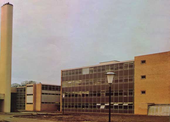
School blocks and the boiler house flue stack associated with the sports block
From Building With Steel, February 1970
Despite poor site conditions and the need to incorporate many types of accommodation these two schools at Middlesborough were built within DES cost limits while exceeding their minimum area requirements. The economy is at least partly due to the adoption of the steel-concrete design as described by Mr K J Caton ARIBA, Assistant Borough Architects (Education), Teeside Authority and Mr R Stainsby DIC, C(Eng), FIStructE, Chief Designer, Teeside Bridge and Engineering Ltd.
This project is planned as a couple of buildings forming two 8-form-entry secondary schools for 2,400 students aged 11 to 16 years and the first stage of this development so far erected and occupied serves 1,800 students.
Each school, with an upper and lower school, has the shared facilities of a sports block containing two gymnasia, a teaching swimming pool and a sports hall along with the communal use of the base playing fields. They will eventually share in the second stage of the development, a hexagonally shaped drama theatre with an associated closed-circuit television studio. The latter will be the hub of a system which, alongside the national circuits, will enable programmes to be mounted from a number of specialist areas within the complex.
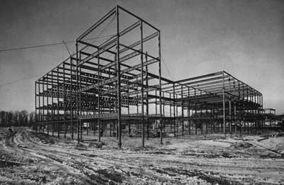
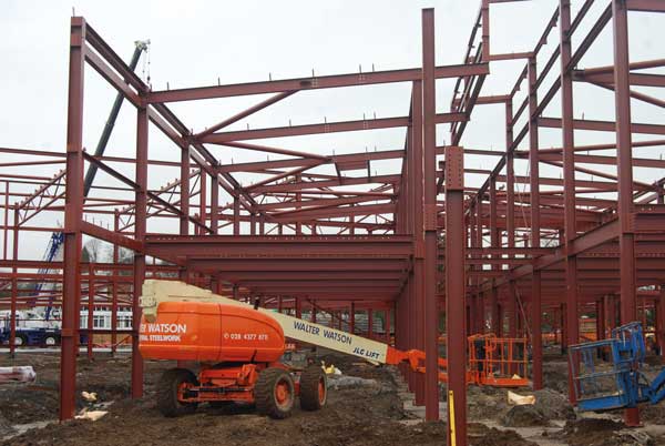
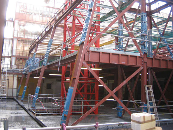
Steel frame showing the 8in diameter holes in the universal beams and the temporary wire bracing ropes
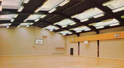
The sports hall showing the steel portal frames
The upper schools have been planned to provide for the full operation of a ‘house system’ where pastoral care and corporate feeling may be achieved with the smaller grouping of students who have opted to continue their studies at these schools rather than transfer at the age of 13 to one of the high schools for continued study through the 6th form courses.
The poor site conditions of silty-sandy substrata with a high water table necessitated the use of the well-point dewatering system for the construction of foundations and the erection the swimming pool above ground level rather than as an excavated construction. The 70ft high over flue stack from the central boiler house consists of a glass fibre casing stiffened by an internal steel lattice frame considerably reducing the ground load. Roofs generally are decked with 3in channel reinforced wood wool slabs which, to single storey buildings and the top floor of 2, 3 and 4 storey blocks are left exposed and decorated. These, along with the relatively light-weight concrete upper floors and insulated steel section curtain walling, have contributed to the necessary aim of reducing foundation loading.
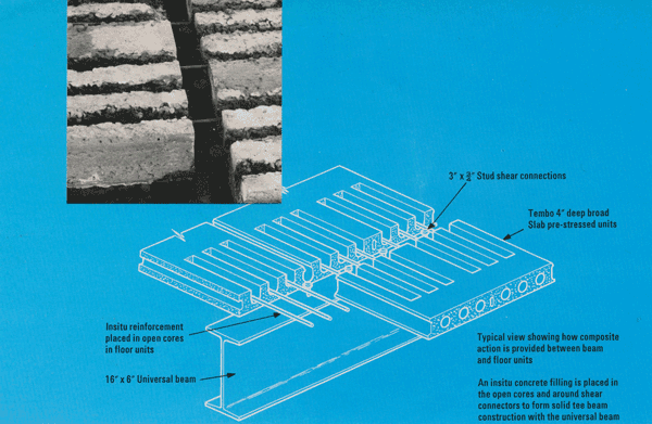
At an early stage, the decision was made to use steel floor beams designed to act compositely with the 4in deep precast floor units. Insitu concrete filling local to the beam made the necessary solid section for composite action.
Using the ultimate load design method from BS Code of Practice CP117 Part I, it was found that a 16in beam could generally be adopted for spans of up to 34ft. Stud connectors ¾in diameter by 3in long, averaging 7½in centres, with ⅜in bar transverse reinforcement ensured adequate shear connection between steel and concrete.
A cost saving was achieved by using more composite construction compared with a more orthodox stanchion and beam construction with bearers. A further bonus is the much stiffer floor support resulting, as the moment of inertia on the combined Tee beam is nearly three times that of the plain steel member.
Stanchions were composed of 6in × 6in or 7in × 7in box sections built up from 6in × 3in and 7in × 3½in channels welded toe to toe. The welded faces were dressed flush in the transverse plane of the building giving a very satisfactory visual result.
Where steelwork remains exposed internally it was important that the connections should be clean and neat, free of bolt heads and nuts. A simple vertical plate connection welded to the column face was used and the webs of the floor beams were site welded to the plate.
A suspended ceiling was necessary in the science blocks to accommodate the considerable quantity of services in the steel beam depth. Beams were planned to be of castellated type to ensure sufficient points for access through them. In the event it proved cheaper to use solid universal beams with 8in diameter holes at 22in centres burnt out of the webs. This had the advantage of leaving a solid web where dictated by the stress conditions without expensive welded infilling of castellation being necessary.
Sufficient brickwork panels were included in the design to ensure lateral stability for each building. The concrete floors serving as horizontal diaphragms to bring wind forces to the stiff panels.
In the erection stage of the steel frame, temporary restraint was provided in the form of ½in diameter steel ropes connected with bulldog clips to steel yokes clamped to the beam or column members. These remained in position whilst floor units were erected and were finally removed as the wall panels were built.
The steel framed sports block, with the gymnasia at first floor level and with the changing accommodation under, has the 100ft × 60ft sports hall spanned by portal frames at 20ft centres. Latticed roof trusses to the swimming pool and gymnasia are in RHS and CHS members shop welded complete.
The present development, with allowance for foundation abnormals, has been carried out within the current Department of Education and Science cost limits. This client has benefited from building areas greater than the minimum laid down and from the special provisions within the sports block. This may be due in no small measure to the economic and efficient contribution of the steel-concrete design.
The first school was occupied 22 months after commencement, the second school 24 months, with overall completion, other than planting and playing fields in 27 months.
Acknowledgements
Mr J V Wall, FRIBA, Borough Architect, County Borough of Teeside.
