
Technical
The provision of shear connectors in composite beams – some code comparisons and subtleties
In this article, Dr Graham Couchman of SCI discusses how design rules have evolved despite the product apparently not changing, and what that means in terms of the provision of studs on a beam. He also identifies some subtleties that could be missed by the designer when specifying studs for use with transverse trapezoidal decking, including their specification to the new Eurocode 4.
Shear connection between steel and concrete elements in composite beams used in buildings has been achieved using 19mm diameter welded headed shear studs for as long as anybody can remember. During that period, for UK design, codes have changed from BS 5950-3.1:19901, to BS EN 1994-1-1:20042, to BS EN 1994-1-1:20263 (published by BSI earlier this year but will not ‘replace’ the earlier document until Spring 2028).
Codified rules have changed, but how much has the physical outcome changed?
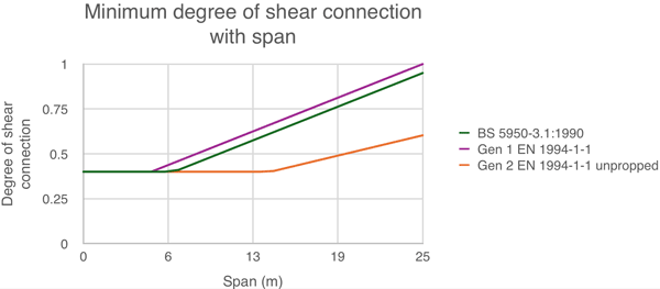
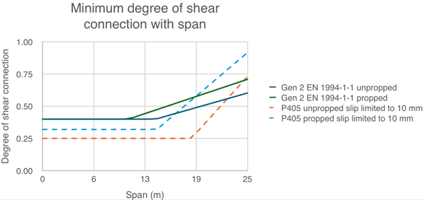
A recent Advisory Desk enquiry from an SCI member still designing composite beams to BS 5950-3.1, which initially concerned us, prompted us to carry out the study described below. Rules for minimum degree of shear connection ensure that enough studs are present on a beam to prevent excess slip between the steel and concrete elements. If we compare the rules for minimum degree of shear connection provided in different codes, and similar guidance, we see some significant differences. These are partly because BS 5950 and Generation 1 Eurocode 4 only recognised three variables, namely span, section asymmetry and steel grade. It should be noted that in order to show historical trends we are not here considering the 2010 Amendment 1 to BS 5950-3.1 which added less onerous rules for so-called ‘higher ductility shear connectors’ in clause 5.5.2.3, although we note in passing that not all software seems to have picked up this amendment. SCI publication P405 Minimum degree of shear connection rules for UK construction to Eurocode 44, and subsequently the Generation 2 Eurocode, took this to another level, also recognising the importance of degree of utilisation in bending, whether construction is propped or not, and that decking orientation affects stud slip capacity. Figure 1 shows minimum degree of connection vs span for BS 5950-3.1:1990, and Generations 1 and 2 Eurocode 4. For clarity, only the case of a symmetric steel section, in S355 steel, with transverse trapezoidal decking (assuming 10mm slip capacity for ‘higher ductility’ studs) is shown. Figure 2 shows the full suite of curves for Generation 2 Eurocode 4 alongside those from P405, assuming a beam utilisation in bending of 80%. The absolute (span-independent) lower bound shown for Generation 2 Eurocode 4 assumes D2 connectors. This could drop to 30% were D3 connectors used, however, research undertaken as part of the development of the new Eurocode suggests higher strength concrete might be necessary to achieve D3 (not less than 10.0mm). As these limits have no scientific basis this subject is discussed no further, but they can cause real problems for mid-range span beams so going as low as possible can be beneficial.
However, the different codes also define different stud resistances, and different effective concrete flange resistances. Given that degree of shear connection is defined as the number of studs provided divided by the number needed to achieve maximum compression in the concrete flange (which may be limited to the maximum tensile capacity of the steel beam), all these variables need to be taken into account to correctly compare codes. That is what Liam Dougherty of SCI has done to create the numbers shown in Table 1, considering the real metric of ‘how many studs do you need on a beam to satisfy the minimum degree of shear connection rules’? Results for S275 steel are included because such steel was the primary choice when the BS 5950-3.1 rules were developed. Results for Generation 2 Eurocode 4 are included even though they could only be justified, according to the code, by using longer studs (115mm with 60mm deck and 135mm with 80mm deck) than we assumed for the other cases. For these examples we did not increase the slab thicknesses in order to retain sufficient cover to the studs, but this could be a knock on effect of needing longer studs (clause 8.6.10.2(2) generally requires 15mm minimum cover, and practically there will be deviations in level to accommodate). The reason for needing a greater length is discussed further below.
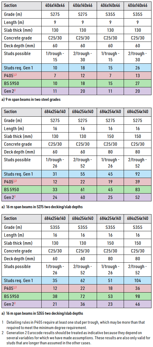
Our conclusions from Table 1 are that, for both spans, BS 5950 and Generation 1 Eurocode 4 give similar result in terms of number of studs needed. For all the longer span cases they require a number of studs that could not be accommodated. Eurocode Generation 2 is generally a marked improvement on Generation 1, notwithstanding the need to use longer studs. P405 allows the use of significantly fewer studs, even compared to Generation 2, but for the 9m span the studs required in all cases could be accommodated anyway, so this is a small gain. For the longer span examples the P405 and Generation 2 improvements are very significant.
Although not evident from the table, this study did reveal something about BS 5950-3.1 that designers using that code (which we would not advocate) should be aware of. The software we used to run these examples appears to have misapplied the code requirements (as well as [conservatively] ignoring the 2010 amendment). The problem is that BS 5950-3.1 Table 5.1 giving solid slab resistances only covers studs up to 100 mm high. However, when its rules (5.4.7.2) are used to determine the reduction in resistance due to the presence of decking, the nominal height of the stud should be used. The software in question does not allow a height greater than 100 mm to be specified (presumably driven by Table 5.1), and is therefore very conservative.
Words of warning about Generation 2 Eurocode 4
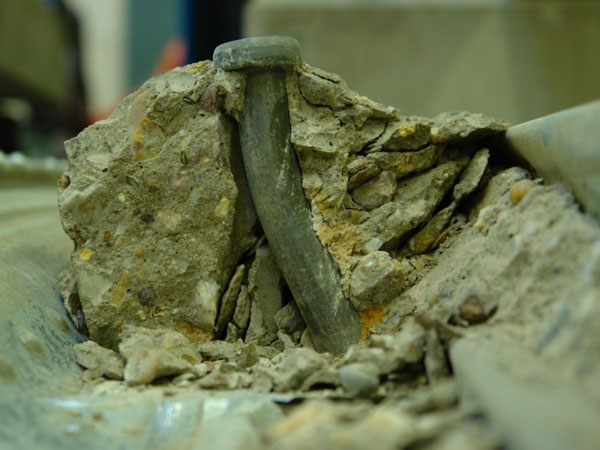
It has been recognised for some time that the way trapezoidal decking has evolved since the early 1990s had made codified rules for stud resistance in transverse decking unconservative. This evolution of shape took place in order to reduce the volume of concrete in a slab, given that the ability of the decking to support the wet concrete during construction often dictates composite slab design. Unfortunately the loss of concrete can also reduce stud resistances. Work undertaken at SCI 20 years ago addressed this problem, leading to the publication of P405. It was also highlighted as something to address when the new Eurocode 4 was being developed. To define new rules a mechanical model was developed at the University of Luxembourg, to try and predict stud resistance. Prediction was previously done through testing and it was hoped a model would have broader application. The model is based on plastic hinges forming near the base of the stud, and at the point where it extends above the decking into the solid part of concrete (Figure 3).
Although using rules based on a mechanical model may be more logical, during the code development process there was a demand to retain the previous approach of reducing the solid slab resistance using a factor kt to keep things simple for designers, where the results of such an approach could be shown to be acceptable. EN 1994-1-1:2026 therefore presents both approaches, with the model-based rules given in Informative Annex G (which the UK is almost certain to reject). Unfortunately, during the re-validation of the reduction factor approach a subtle change was deemed necessary, which is to increase the required embedment length of stud above the decking. A dimension of 2.0d in the Generation 1 document was extended to 2.7d. The variable d is the stud diameter, so for 19 mm studs, 38 mm went to 51mm. That means that typical UK construction using a 100mm stud with 60mm decking can no longer be designed using the simple kt approach – a subtlety that may be missed by users of the new code.
With Annex G very likely to be rejected, and the reduction factor rule not applicable to much typical UK practice, where does that leave us? Thankfully there are two options.
- BS EN 1994-1-1:2026 explicitly states that test-based values can be used as an alternative. That means existing SCI guidance such as P405 can continue to be used.
- An alternative Annex G is being developed by Prof Stephen Hicks at the University of Warwick, that should provide more robust results than those given in either part of the code.
When is transverse decking not transverse decking?
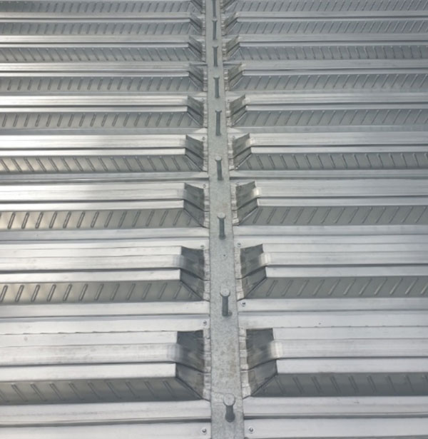
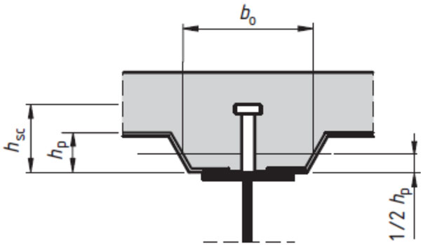
The discussion above relates to studs used in conjunction with transverse trapezoidal decking. In many cases (at least in the UK) the decking will be continuous across the beam flange, and the studs will be through deck welded. Making the decking continuous is beneficial because it reduces its deflection under wet concrete, and has process benefits. However continuity is not always the case – separate spans of decking may be used either side of the beam, often with so-called crushed ends (Figure 4). When this approach is adopted it means the detrimental impact of the voids ‘ahead’ of the studs, that the kt factor is supposed to reflect, is not present. Depending on the geometry of the crushed ends, flange width and decking depth, the stud may then find itself in a situation more like that of a stud with parallel decking (Figure 5). It may then be appropriate to adopt the parallel decking reduction factor kl, which often results in no reduction from the solid slab resistance. When using software designers should be aware of this, as some software does not recognise the difference between continuous and discontinuous decking and so penalises the stud resistance. Such penalisation could result in an erroneous failure to satisfy minimum degree of connection.
Conclusion
The shear stud is wonderfully simple, and simply wonderful (in that it can double the resistance of a steel beam and increase the stiffness threefold). But designers should be aware of some complexities and subtleties when designing composite beams.
References
- BS 5950-3.1:1990 Design in composite construction. Code of practice for design of simple and continuous composite beams. BSI, 1990
- BS EN 1994-1-1:2004 Eurocode 4: Design of composite steel and concrete structures. General rules and rules for buildings BSI, 2004
- BS EN 1994-1-1:2026 Eurocode 4: Design of composite steel and concrete structures. General rules and rules for buildings BSI, 2026
- COUCHMAN, G. Minimum degree of shear connection rules for UK construction to Eurocode 4 (P405) SCI, 2015