Projects and Features
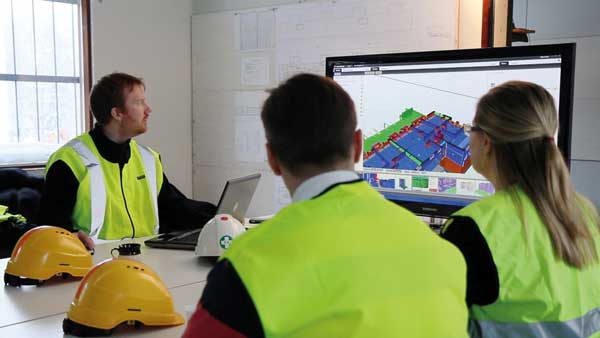
Modelling for project success

Wembley Stadium steelwork model, courtesy of Oakwood Engineering, showing 4D information retrospectively added to the model for visualisation of critical project dates.
Developments in Building Information Modelling have moved on in leaps and bounds in recent times. Andrew Bellerby, Managing Director of Tekla (UK), explains how structural models provide added value to construction projects.
The structural steel segment has always been ahead of the main building and construction industry players by adopting 3D modelling technology. Even though we are approaching twenty-years of 3D product modelling, many companies still only use the model data for the production of 2D fabrication drawings; for feeding their MIS systems and for producing NC data. However, many companies are realising that the potential usage of the structural model data is actually far greater.

Complicated steel- work designs, such as Wembley Stadium, have been made easier thanks to 3D modelling packages.
Companies are now starting to wake-up to the power of the rich data within the structural model and where else it can be used within their internal processes. They also are discovering how structural models allow them to provide additional added value to the projects they are working on. While Building Information Modelling (BIM) as a practise and a process is becoming more commonplace, the structural model, provided by the steelwork contractor, becomes the normal “as-built” project model, as it contains the exact quantities and precise information required for successful completion of the project and so it has become one of the most vital parts on every project.
Who can use the data within the structural model and how?
We have already seen CNC machine manufacturers such as Ficep, with their partner Steel Projects, making use of the Tekla Open API provided with
the Tekla Structures software. The application programming interface was utilised to develop a link to extract information from the model to drive their scribing tools and start to move the steelwork industry towards a potentially paper-free workshop.
Another example would be Richard Lees Steel Decking, who have developed a solution for placing the structural decking into the structural model. This allows them to take all the connection materials
into account, which they would not previously
have easy access to. Other key benefits include being able to “fly” under the deck and identify areas where additional supports are required. The decking sheets can now be downloaded to a laser cutting machine directly from the model, moving the cutting of the deck offsite.

Trimble Total Sta- tion displaying the drawing and survey control points.
More recently, a bi-directional link between Tekla Structures and Leighs Paints’ FIRETEX software
has been developed to improve the somewhat time consuming task of fire protection paint calculations. The link will enable information to be passed between the software packages allowing the user to transfer geometry and information regarding the steel structure with speed and accuracy at the click of a button. The FIRETEX software then calculates the required coating thickness based on the information from the model and the required fire ratings, these thicknesses can then be inserted directly back into the model, saving valuable time, providing more accurate paint volumes, and reducing the possibility of errors within the current workflow.
RFID Technology in Construction
The use of bar-coding in manufacturing in the construction industry has never really taken off in a big way, limited often on the shop floor by paint, grime and damage to the bar code stickers themselves. Radio Frequency Identification (RFID) certainly has the potential to take this type of technology to the next level, providing status information of parts, not only in fabrication workshops, but also on the construction site, as well as providing other advantageous information.
RFID technology can give “real time” status information at all stages of the manufacturing and erection processes. Vela Systems (www. velasystems.com) have been working with Tekla to synchronise the status information provided through their RFID software with the Tekla Structures building information model. At each stage of the fabrication, despatch, shipping and erection processes the tags can be read either by scanning manually or by automatic readers positioned at strategic locations.
This information can then be uploaded to a
web server at regular intervals. The uploaded data on the web server is synchronised with the Tekla model to provide a visual representation of the 4D (time) project status. This ensures critical aspects
of supply chain management and co-ordination be- coming centralised in the model. Powerful filtering and visualisation tools in the Tekla software allow the running of simulations and analysing “what if” scenarios to minimise risk and take advantage of the data previously not so readily available. The po- tential time-savings on projects are huge.

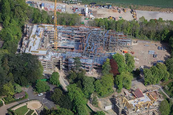
The use of 3D models, on projects such as More London plot 7, was critical for the completion of offsite cutting of metal decking.
Data Storage by CE Marking
As RFID technology evolves it offers many more options for data storage that could be tagged to the constructed parts for ongoing facilities manage- ment. CE marking for the steelwork industry is leg- islation that we all need to deal with, and the RFID technology certainly opens up new options for stor- age of associated information.
While many companies will adopt a method of adding the CE marks to drawings and other docu- ments, there is no reason why design or procure- ment information for example could not reside in the building information model and also on the individual parts by means of an RFID sticker, which of course would still be able to be read even if the stickers are painted over.
Tekla with Trimble on Site
Site planning, design co-ordination, and crane posi- tioning are already utilising the 3D interface and the 4D schedule that is associated with the model parts. Development between Tekla and Trimble (www. trimble.com) now takes the Tekla model information into the Trimble Robotic Total Station to simplify the surveying and layout tasks. Tools have been devel- oped so that a survey path and control points are defined in the model. This co-ordination and other information can be exported to the Robotic Total Station, along with a DXF file of the arrangement drawing, visually showing the same information. The site layout can then be carried out by one person as the information from the Total station is transmitted by radio, the control points are shot, the site features measured, and all project set out points created. This gives an accurate as-built vs. as- designed survey with the information brought back into the model for reporting and tracking. Any re- work is minimised and potential error prone manual calculations are eliminated.
Conclusions
Any streamlining of existing practises and proc- esses will help minimise costs, which is essential for every company and for every project in the cur- rently economic climate. Making better use of the rich data in the structural model is certainly one way of ensuring that this will happen. The building information model can empower and improve many of the processes currently executed, minimising replication of data input and providing accurate in- formation to help manage projects more effectively and therefore help reduce risk and costs.