Projects and Features
Levelling up
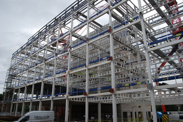
A steel-framed office development in Darlington will provide a regional economic boost and act as a catalyst for further regeneration.
FACT FILE
Darlington Economic Campus
Main client: Government Property Agency
Architect: Ryder Architecture
Main contractor: Kier
Structural engineer: Cundall
Steelwork contractor: Elland Steel Structures
Steel tonnage: 800t
Supporting the government’s commitment to regional growth, a five-storey office development in Darlington town centre will on completion accommodate more than 1,600 civil servants.
Located on Brunswick Street and providing a permanent home for the Darlington Economic Campus (DEC), the steel-framed building will bring together teams from six government departments, including HM Treasury.
A visible sign of investment into the North East, the campus forms part of the Government Hubs Programme, supporting economic growth across the UK through the redevelopment of brownfield sites or repurposing existing buildings to create efficient, sustainable and productive workplaces.
Simon Hulme, Director of Capital Projects at the Government Property Agency (GPA), says: “This development is a hugely significant programme for the GPA as we continue our ambition to provide great places to work for the Civil Service.
“Once complete, this building will be a modern, sustainable and digitally-enabled office space.”
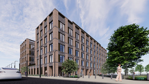
Fulfilling the client’s wish for a design with the least amount of embodied carbon, a steel frame supporting metal decked flooring was chosen as the solution for this project.
However, not completely satisfied with the design, the project team had an opportunity to improve and rationalise it by undertaking a design optimisation process.
“Initially, the building had a central atrium and four cores, dotted around the structure,” says Kier’s Senior Project Manager Conor O’Keeffe.
“By combining the lift shafts, stairs, toilets and service risers into one large core, placing it in the middle of the building, instead of the atrium, we’ve made better use of the available floor space.”
The steel frame gains its stability from the re-positioned core, by surrounding and connecting to it via cast-in plates. The frame is based around a 7.5m × 9m grid, which is said to create an optimum and efficient set of floorplates with minimal internal columns.
“The original design had secondary beams at 2.5m centres,” explains Cundall Associate Stuart Mark. “We stretched the metal decking to span 3.75m, which rationalised the design even more.”
Prior to the steelwork erection, the brownfield site, which had previously accommodated a tannery, light industrial units and most recently a car park, was fully remediated.
Once the ground was made ready, piled foundations, up to 27m-deep, were installed and then the core and the ground floor slab were cast.
Installing the ground floor slab early-doors, before the building’s main frame is up is not always the way to go. But on this job, Kier decided it was a good idea, as it provides a flat and safe surface for the steel erector’s MEWPs, and guards against inclement weather turning the structure’s footprint into a muddy quagmire.
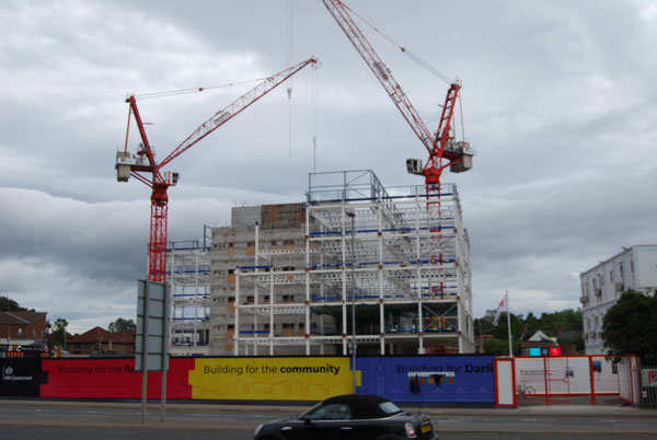
Using the site’s two tower cranes for all lifting duties, Elland Steel Structures erected the building in four phases. Each phase saw the building erected to its full height, with columns spliced at third floor level. Once each phase was erected, the area was handed-over to the flooring subcontractor.
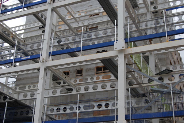
The composite flooring is supported on Westok cellular beams throughout the structure. As well as providing an efficient steel solution for the internal spans, the beams also accommodate the building services within their depth. Adding some architectural interest and creating an industrial-looking interior for the offices, the beams will be on show in the completed building.
James Way, ASD Westok Technical Advisory Engineer on the scheme, commented: “The Darlington job is one of a number of commercial office schemes Westok has on site at present. On this project, the Westok beams were typically 600mm deep with regularly spaced 400mm-diameter cells. Certain beams were also provided with elongated cells to facilitate the efficient passage of wider rectangular services.”
The ground floor of the development is the only level that occupies the entire footprint of the structure. Beginning at first floor and extending to the full height of the building, there are two set-backs or indents within the steel frame.
Located on the north and south elevations, the indents create two small terraces at first floor level. Transfer beams (weighing 7t each) support the change in column positions to the north, while columns have been coordinated with the architectural layout to the south to avoid additional transfer structure.
Office accommodation is located on each of the four upper levels of the building, while the ground floor, which has a slightly higher floor-to-ceiling height, has the main entrance and lobby (a small double-height space), meeting rooms, plant rooms (there is more plant on the roof) and a conference facility.
Located along the north elevation of the building, the conference facility is a column-free space measuring approximately 21m × 14m. It is formed with two plate girders positioned at first floor level, which support the column lines that begin above the conference area.
The 14m-long × 1,200mm-deep girders each weigh 16t and are the heaviest steel elements on the project.
Adding some flexibility to the overall design, the conference room will feature two moveable partitions, allowing it to be subdivided into three areas, or left as one large space.
Attached to the ground floor and running the length of the southern elevation, the main entrance will benefit from a covered colonnade. Measuring 22m-long × 3.75m-deep, the covered area will be supported by a series of precast concrete clad steel columns.
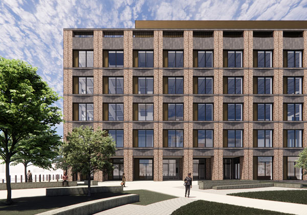
The robust exterior design also extends to the building’s main facades, which will be clad in precast panels (with a brick slip facing), supported from bracketry attached to the steel frame.
Summing up, Lola McEvoy, Member of Parliament for Darlington, says: “Darlington is the Number 11 of the North and the new Government Hub will be a big boost for the town. It’s great to see the steelwork going in. I’ve been working hard to make sure this government investment benefits the town’s business community, construction supply chain, and workforce, as well as brings new people to Darlington.
“This government project has benefited us already by using regional contractors, and once it’s built everyone who works there will have the same terms and conditions, from building services staff to senior civil servants. Quality, reliable jobs for people in our town and several government departments located in Darlington – what’s not to like!”
Cast-in plates: connecting steel to concrete
At the Darlington Economic Campus, cast-in plates connect the steel frame to the concrete core. It is a common detail, but one that sits on the boundary between two materials, two specifications and usually two designers. Liam Dougherty of the SCI explains what to consider.
A cast-in plate is a steel plate embedded in the face of a concrete wall, with shear studs and reinforcing bars welded to its rear face. The studs transfer the vertical reaction from the supported beam into the concrete in shear, while the reinforcement resists tension arising from connection eccentricity or a robustness tie force. The beam is commonly connected via a fin plate, welded on site to the cast-in plate after the concrete has been cast and its position surveyed.
The fin plate itself is no different from a standard simple connection to a steel column; what changes is the support, which is now a plate anchored into concrete rather than a column flange. Standard simple connections assume that vertical shear and the robustness tie force act in separate load cases. Where the floor slab continues to the core wall, tie forces can preferably be transferred through the slab reinforcement into the core. This distributes the force rather than concentrating it at an individual beam connection, making the required tying resistance easier to develop.
Connections subjected to simultaneous shear and axial force require particular care, as they fall outside the standard simple-connection model. Alternative detailing and a specific design assessment may be needed to ensure the connection transfers the combined forces into the core.
Construction tolerances are another key consideration. Cast-in plates may deviate from their intended positions, while wall inclination can increase the resulting misalignment. Plates should therefore be surveyed once the concrete has been cast, and fin plates detailed to suit their as-built positions. The connection must accommodate the resulting eccentricity and allow sufficient clearance for beam rotation.
Design responsibility is typically divided at the face of the concrete wall. The structural engineer establishes the design forces and tolerances and checks the wall for effects including punching shear and bearing. The steelwork contractor typically designs the fin plate connection in accordance with the agreed design principles. Both parties must coordinate their assumptions to ensure the complete connection performs as intended.
Standard fin plate details are given in SCI P358, Joints in Steel Construction: Simple Joints to Eurocode 3. SCI P416, The Design of Cast-in Plates, complements this guidance by covering the cast-in plate, its shear studs and reinforcement, and the supporting concrete wall. It also provides a design model, a step-by-step procedure and a worked example.