
Projects and Features
Deflections of steel frames in fire – don’t be misled by simple calculations or the Cardington tests
Dr Graham Couchman of SCI aims to show why there are currently no easy answers to the question of beam deflections in fire, but there are many reasons why some of the simple assumptions being made, that can result in alarming numbers, should be questioned.
Analysis of the subjects SCI’s Advisory Desk gets asked about shows two very clear things, firstly that connections are always top of the list (at over 20%), secondly and not surprisingly that fire is on the increase and may soon reach the ‘number one spot’. Most of the fire-related questions concern justifying methods and rules that have been common practice for decades. One featuring heavily at the moment is whether it is necessary to calculate deflections of beams in a fire condition, with particular reference to the ability of deflection heads on non-loadbearing compartment walls to accommodate the movements they will experience.
Although at SCI we like to provide answers, indeed we survive because we provide answers, in this ‘scene setting’ article Dr Graham Couchman of SCI aims to show why there are currently no easy answers to the question of beam deflections in fire, but there are many reasons why some of the simple assumptions being made, that can result in alarming numbers, should be questioned.
Introduction
When considering how to predict the deflections of a structure in fire, a fundamental issue is that fire tests are performed on elements – for example walls and floors. Calculations ‘suffer’ from the same limitation, as much of the analysis and design of a structure relates to individual elements in order to verify the resistance and deflection of simply supported beams, resistance of column lengths etc. Predictions of elemental behaviour obtained in either of these ways cannot be used to predict the performance of a system in fire. For example, a steel beam connected to columns at either end, and a floor slab, will have some end continuity (that is ignored for ambient design in the interests of design simplicity and because an ‘acceptable’ result can be obtained), and with bracing limiting lateral movement of parts of the structure may be subject to ‘pre-compression’ and thermal bowing when exposed to fire. All this context will affect the individual beam’s deflection. Predicting the performance of a system at elevated temperature through calculation is impractical (and indeed for most designers impossible). Determining the performance of a system at elevated temperature by test is prohibitively expensive – the tests performed at BRE’s Cardington site in the mid-1990s are a rare example. Full details of these tests were made available 1, and they form the basis of SCI guide P288 2. They are discussed further below.
What about Cardington?
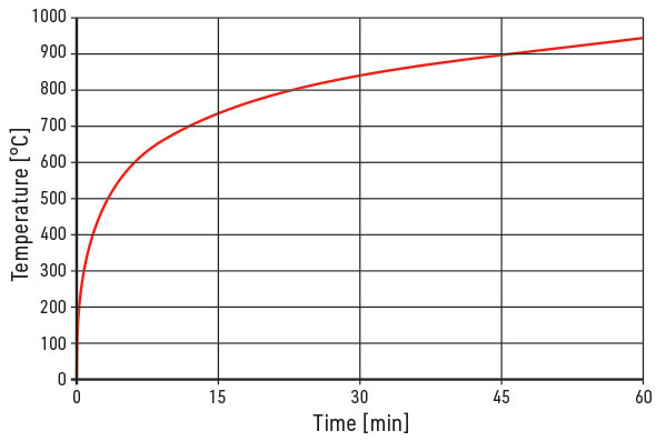
Before talking about the Cardington tests specifically it is worth pausing to consider the standard ISO fire (Figure 1), as adopted by the Eurocodes. In the Cardington tests timber cribs were used as fuel in an effort to mimic the time-temperature curve resulting from such a fire. The standard ISO fire curve is not supposed to represent the fire a building would experience. An obvious giveaway that it does not reflect reality is that there is no cooling down phase. It is a standard fire intended to be used to demonstrate the comparative performance of similar elements in standardised tests. Real buildings will not experience an ISO standard fire, and therefore will not experience the temperatures and magnitude of deflections found in some of the Cardington tests.
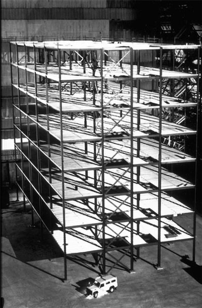
Considering the tests themselves (Figure 2), which took place in parts of an eight-storey steel-framed building with composite (re-entrant decking) floors, some readers may be familiar with the photographs that showed huge deflections following testing. These were three figures (in mm). Whilst they illustrate one of the reasons why the Cardington tests were considered to be such a success – because a steel framed composite floor multi-storey building was shown to be sufficiently robust to undergo massive deformations without collapse – they are not helpful to discussions on how large beam deflections in a real situation could get. Firstly because they were deflections of unprotected beams, which are not commonly used in practice, and secondly because of the imposed fire. Both these facts mean the beams in question reached much higher temperatures than would be expected in reality. The Cardington tests are a very useful source of comfort when it comes to considerations of building collapse in fire, but are not helpful when considering deflections, and deflection head requirements.
It is worth adding a comment on P375 3, which suggests that ‘for convenience’ a deflection of span/20 should be considered. We won’t get distracted as to why it suggests 20 and P288 suggests 30, other than to note that P375 relates to steel beams and P288 to composite beams, because clearly it would be very inconvenient to detail a deflection head to cope with deformations of either magnitude. So although it was presented as a simple and conservative rule to cover all cases (protected beam or not, wall crossing under beam in span or beneath beam) we would advise against directly following this guidance when considering deflection heads. Indirectly it may be used to identify locations where deflection head requirements will be relatively low, locations at which compartment walls should be placed if possible.
What else do we know?
If we return for a moment to thinking about elements (beams), we know steel and concrete expand with heat. This results in two phenomena – end connections behave as if fixed in the fire condition (reducing deflections ‘due to bending’ by a factor of five compared to simple connections), and because of temperature gradients (decreasing bottom to top) and material properties beams will undergo thermal bowing. This bowing results in downward movement in span that is the greatest contributor to deflections in fire. We can conclude that simply ‘extrapolating’ ambient temperature results to cover the fire situation, by using reduced material properties, is therefore incorrect. It is worth noting that this complication applies to concrete structures just as much as for steel framed buildings, so choosing an alternative framing material does not remove the requirement to consider deflections in fire.
As an alternative (or perhaps supplement) to thinking about how to avoid failure of compartment walls, it may be worth considering the consequences of failure. Much of the steel frame market comprises commercial buildings, which have multiple escape routes and are likely to have a fire strategy that involves evacuating a complete floor, and the floor above, in the event of fire. Remembering that the purpose of fire regulations is to protect occupants and those fighting the fire, there may be cases where the consequences of compartmentation failure are deemed sufficiently low to justify the use of engineering judgement on deflection heads. If that is unacceptable then the use of load-bearing compartment walls would be one way to avoid the complex problem of predicting deflections, although justifying the extra cost could prove to be equally difficult. A ‘stay in place’ fire strategy would clearly be a completely different proposition, highlighting that the elevated temperature design of a building and its fire strategy should not be treated independently. The use of sprinklers may be part of that strategy and have some relevance to deflection head requirements.
Conclusions
Consideration of all of the above shows why, choosing just two examples, SCI members are contacting us with feelings of frustration. These two examples come from members who play very different roles in the delivery of steel framed buildings. One was a decking manufacturer who was asked to say how much a slab using their deck would deflect in fire – how could they know? The second was from a consultant (frame designer) complaining how unreasonable it is for main contractors or architects to expect them to predict deflections that can be used to specify deflection head requirements – an activity that is way beyond their remit (and for many such companies, their abilities). The frame designer also correctly noted that perhaps there is an incompatibility between wanting certified performance (from tests) and using steel structures, which is clearly a concern for the sector. We would argue that the answer to this incompatibility comes from giving more thought to the problem, not from avoiding using steel frames (which provide so many benefits as witnessed by their dominant market share for many applications). This argument is reinforced if we consider that thermal gradients in concrete structures will also result in behaviour that cannot be quantified through traditional structural engineering methods.
In the absence of further information, which we hope to obtain in due course, we would conclude that a requirement of 40 mm for deflection head travel has been expressed in Approved Document B 4 for 20 years, and we suggest a combination of the apparent ‘success’ of that requirement combined with lots of reasons why simple calculations suggesting the number is wrong are themselves easily shown to be wildly incorrect, support its future use.
References
- The behaviour of multi-storey steel framed buildings in fire – a European joint research programme. British Steel Swinden Technology Centre, 1999
- P288 Fire Safe Design: A New Approach to Multi-Storey Steel-Framed Buildings (Second Edition), SCI, 2006
- P375 Fire resistance Design of Steel Framed Buildings In accordance with Eurocodes and the UK National Annexes, SCI, 2012
- The Building Regulations 2010: Approved Document B – Fire safety (Volumes 1
and 2). The Stationery Office