Projects and Features
Mayfair in the frame
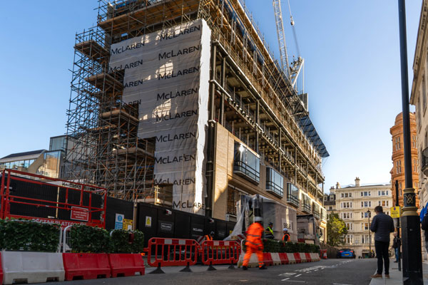
Structural steelwork has provided a prestigious central London address with the desired flexible, modern and column-free floorplates.
FACT FILE
11-14 Grafton Street, London
Main client: O&H Properties
Architect: Foster & Partners
Main contractor: McLaren Construction
Structural engineer: Ramboll
Steelwork contractor: BHC
Steel tonnage: 600t
Commercial and retail developments do not come any more prestigious than a scheme in London’s Mayfair district. Bounded by Piccadilly to the south, Oxford Street to the north, and Park Lane and Regent Street on its western and eastern sides, the area has historically been the capital’s prime location for wealthy residents and high-end shops.
One thoroughfare in particular (Old and New Bond Street) is said to be the most expensive and sought after strip of real estate in the world. Bisecting Mayfair, north to south, the street has been home to upmarket and exclusive retailers for over 200 years.
Building on Bond Street’s history, developer O&H Properties is constructing a large mixed-use development on the corner with Grafton Street. Initially, it comprises a flagship retail and office development, but later phases will include new homes and a five-star boutique hotel.
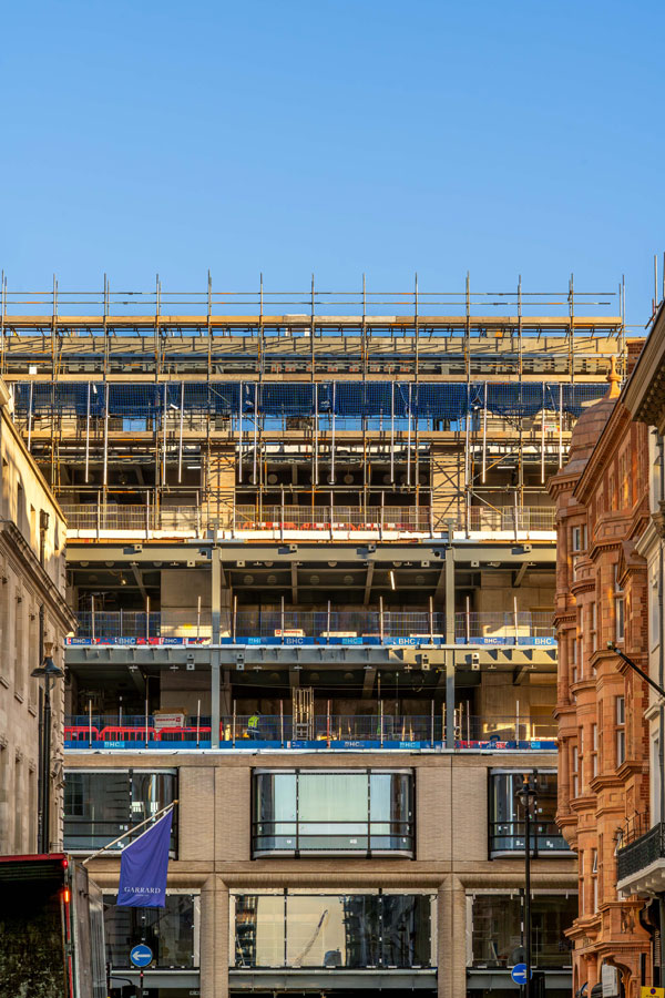
Designed by Foster & Partners and being constructed by McLaren Construction, the £60 million project will provide 5,400m² of floor space within its seven-storey steel frame.
Work onsite began in 2023, with the demolition of the previous 1960s-built office block. After the plot had been cleared, one of the first elements to be undertaken was the excavation of the scheme’s new three-level basement.
To enable the basement works package to be carried out, the central portion of the ground floor slab and the main concrete core were first installed, followed by the two outer precast cores.
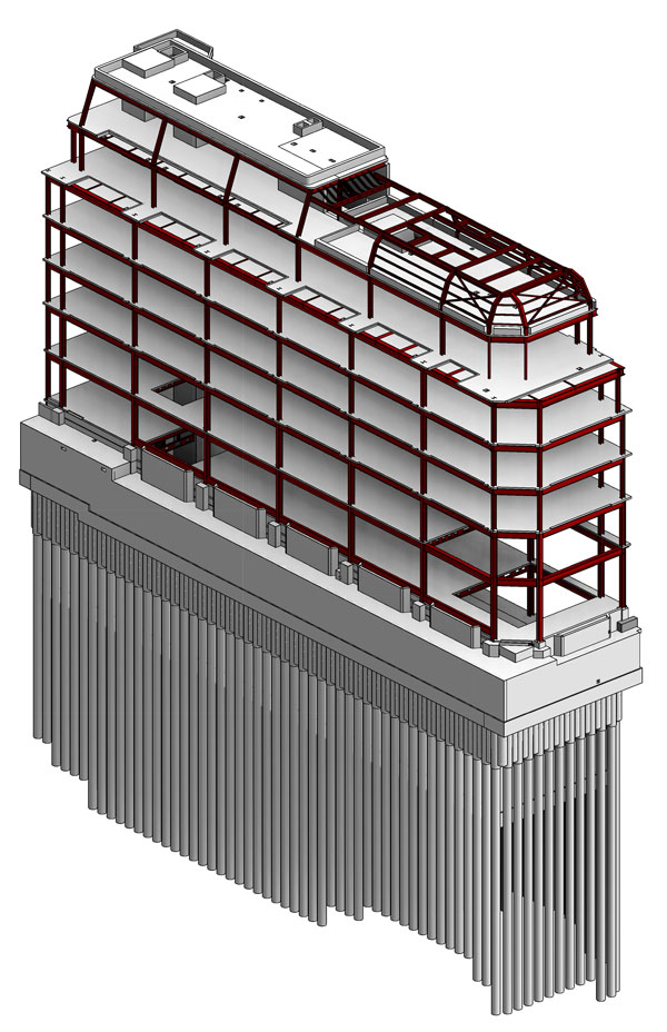
In preparation for the excavation, an extensive temporary works package was needed, which included the installation of 33m-deep × 1.2m-diameter piles, to support the main steel frame. A series of 15m-deep plunge columns were also installed to support the project’s tower crane steel grillage.
The steel frame’s main columns begin at lower ground level and extend upwards to the roof in spliced sections. Each column is two floors high, as the length of the steel sections was limited by the confined nature of the site.
“The project is on a tight corner and our delivery trucks could only negotiate the surrounding streets with loads of up to 14m in length,” explains BHC Project Manager, Eddie Brown.
As well as the impact on the steel sizes, the location required extensive coordination and planning. McLaren worked closely with the City of Westminster to develop a logistics strategy and traffic management plan to minimise impact on the local road network.
Like many inner-city construction sites, this project has had to work around a number of constraints. Aside from the narrow and busy surrounding streets, the southbound Victoria Underground line and the culvert for the Tyburn River run directly beneath the site, a major sewer is under the New Bond Street pavement, and to the north, the new building abuts an historic party wall. Monitoring of all these assets has been ongoing throughout the construction programme.
Helping to minimise the impact on the local traffic, once the steelwork arrived at Grafton Street, it was temporarily stored, before being erected, on an adjacent and vacant plot (the site of the forthcoming hotel).
As well as being used for the storage of materials, the empty plot was also used to position a mobile crane, which undertook steel lifting duties (in order to maximise programme efficiency) alongside the site’s tower crane.
Ensuring the limited onsite storage space was not overloaded, the steelwork was delivered on a just-in-time basis and erected almost immediately.
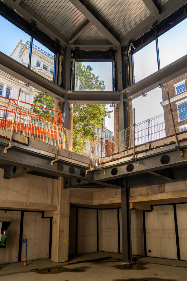
Based around a regular grid pattern, the steel frame’s perimeter columns are spaced at 8m centres and support floor beams that span the entire 12m-long width of the building, without any additional internal support.
“As the building is quite narrow, column-free spans were essential in order to make the building’s floorplates as efficient as possible. We also wanted to integrate the building services within the slimmest floors, to maximise the floor-to-ceiling heights within the structure’s permitted height,” explains Ramboll Director for Buildings, Sheena Patel.
“After looking at various framing solutions for the project, steelwork was the best option.”
The use of structural steelwork has also provided the client and future tenant with some flexibility. Lower ground, ground and first floor are envisioned as retail levels, with all of the upper floorplates accommodating offices.
However, this floorplate layout does not have to be permanent, as the building’s steel frame has been designed and constructed to allow every floor to be retail level or an office space. As retail floors are typically designed to accept higher loadings, all of the floors have been designed with the appropriate higher capacity.
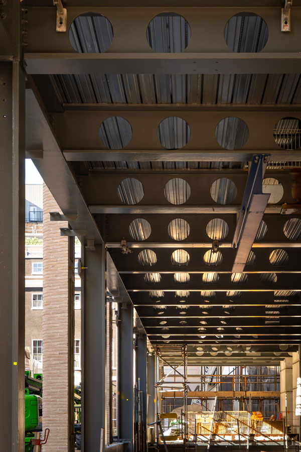
Fabricated by BHC, the floor beams are plate girders that have bespoke cellular openings to accommodate the building services. A lot of coordination was needed, between the steelwork contractor and the MEP companies, to make sure each opening was the correct diameter.
The beams support metal decking and a concrete topping to form a composite flooring solution for every floor above ground level.
Providing the frame’s necessary stability, steel beams are connected to the three concrete cores via cast-in plates, embedded into the concrete structures.
The cast-in plates feature a bespoke bolted connection, which reduces the need for welding work to be carried out at height and consequently speeds up the construction programme.
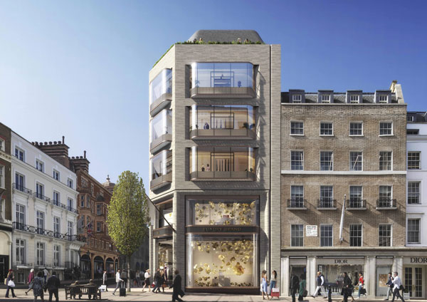
In order to sit comfortably within the Mayfair Conservation Area, the building has a precast concrete and brick façade and curved triple-glazed windows.
Secondary steelwork that supports the cladding and windows is connected to the main steel frame via a series of brackets, which were pre-welded to the beams and columns during the fabrication process.
McLaren Construction Project Director, Olly Rowsell, comments: “Early on in the design process we decided to omit the complex facade bracketry from the façade contractor’s brief and include it within the primary frame package with BHC.
“This allowed us to manage a very key interface and maintain absolute accuracy by allowing BHC to design, model, fabricate and most importantly complete the intumescent paint to maintain full compliance with one trusted partner.”
Coordination between the project’s sub-contractors, was key to the successful manufacture and positioning of these brackets.
BHC designed the brackets in line with the loads and dimensions provided by the relevant sub-contractor’s drawings. For the precast cladding panels, the brackets are generally fabricated 20mm-thick plates, with square holes for their lateral restraint fixings and cantilever posts providing the support.
For the windows, pre-welded 20mm-thick self-weight brackets, with lateral restraint sections, were supplied.
Topping the building, the two uppermost floors step back accommodating terraces and a rooftop event space, topped with a zinc shingle roof.
The terrace’s inset column lines are supported by heavier floor beams that act as transfers, negating the need for another column within the building.
The roof also houses an external plant area, which is enclosed by a galvanized steel surround.
11-14 Grafton Street is due to complete in February 2026.
Cast-in plates
The Grafton Street project uses cast-in plates to transfer the loads through the floor structure to the concrete core. Bogdan Balan of the SCI offers his thoughts on using these and the design issues to consider.
Cast-in plates are a critical component to the interface between steel frames and concrete core walls, particularly in the UK, where concrete cores are commonly used for lateral stability. The cast-in plates allow the transfer of vertical, horizontal, and tie forces from steel beams into the concrete structure. Despite their widespread use, the absence of standardised design guidance has historically led to inconsistent detailing and ambiguity in responsibility allocation across projects. The introduction of a unified design model, as outlined in SCI P416, addresses these challenges by providing a consistent framework for design and construction.
Cast-in plates are typically designed to function as nominally pinned connections in simple construction, consistent with the principles described in SCI P358 and BS EN 1993-1-8. In such configurations, vertical shear is resisted by shear studs welded on the back of the plate, while axial forces are transferred via reinforcement bars. These bars are welded to the plate and rely on bond strength with the surrounding concrete to develop the necessary tensile resistance, in accordance with BS EN 1992-1-1. In cases where connections must resist both shear and axial forces simultaneously, standard detailing may be insufficient. Alternative arrangements, such as the use of tension plates and torsional restraints, are required to prevent the development of unintended bending moments and to preserve the intended pinned behaviour.
The performance of cast-in plates is highly sensitive to construction tolerances. Both concrete and steel elements are subject to positional and rotational deviations, due to the characteristic irregularity in the construction processes. National specifications such as the National Structural Concrete Specification (NSCS) and the National Structural Steelwork Specification (NSSS) define acceptable limits for these deviations. For example, a lateral deviation of ±35mm in the position of a cast-in plate can significantly modify the distribution of shear forces among the studs, potentially exceeding their design resistance. Consequently, it is essential that the design accommodates the worst-case positional scenarios. Surveying the as-built location of cast-in plates prior to finalising fin plate detailing is a critical step in mitigating the impact of these deviations.
The effective design and implementation of cast-in plates demand a comprehensive understanding of their structural role, the implications of construction tolerances, and the behaviour under complex loading conditions. If considering or detailing cast-in plates, designers are recommended to consult the guidance in SCI P416 and divide the design responsibilities for the connection according to the level of information held by the relevant parties.