Projects and Features
Just the ticket
Structural steelwork has provided the framing solution for the Haverfordwest Public Transport Interchange, which includes a bus station and multi-storey car park.
FACT FILE
Haverfordwest Public Transport Interchange
Main client: Pembrokeshire County Council
Architect: BDP
Main contractor: Kier Construction
Structural engineer: BDP
Steelwork contractor: William Haley
Steel tonnage: 620t
It’s all change in the county town of Haverfordwest, as the local authority Pembrokeshire County Council has a number of redevelopment schemes underway that will improve the visitor experience, increase footfall and upgrade transportation links.
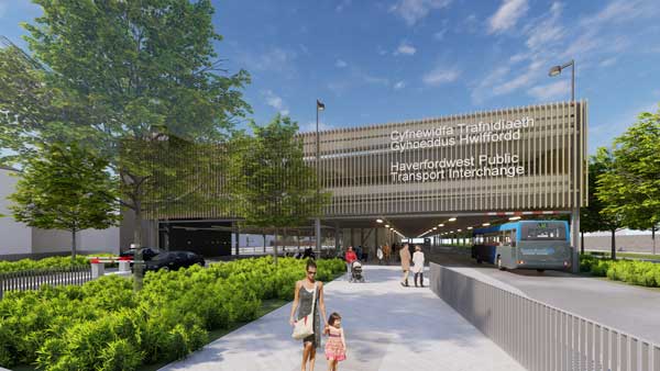
Central to its regeneration plans is the £13.9 million Haverfordwest Public Transport Interchange, which will provide a more convenient way to arrive and depart from the town for residents and visitors alike.
The scheme forms part of the South West Wales Metro project and will provide a modern and innovative transport hub, integrating all modes of transportation.
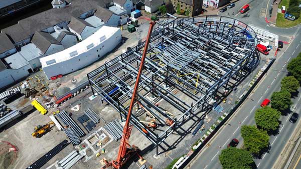
Located on a plot previously occupied by a multi-storey car park, the new steel-framed facility will accommodate a ground floor six-bay bus and coach station, with a waiting hall, office and retail units, alongside 280 car parking spaces (mostly on the two upper decks).
Work on the project began in November 2024, with the early works including the installation of CFA piles, which are up to 13m deep.
A clash detection programme was undertaken prior to this work being carried out, as the previous structure’s piles remain in the ground and the new foundations had to be designed and installed around them.
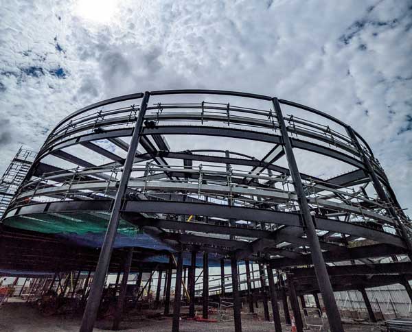
The new piles and ground beams support the steel superstructure, which measures 120m-long x 40m-wide and is 15m-high. Because of the length of the building, a movement joint across the middle of the structure has been included to reduce the effects of thermal shrinkage and expansion.
Commenting on the choice of a steel-framed option, Kier Construction Project Manager Dean Williams says, the material was chosen for its speed of construction, and because it can easily form the long internal spans required for the interchange.
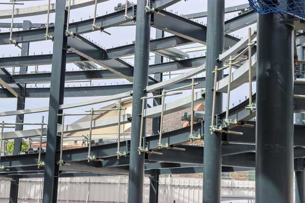
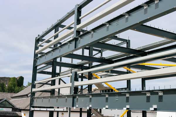
To this end, the steel frame is designed around a 16.7m x 7.5m grid pattern, with three rows of internal columns, located in the middle of the structure. This provides the building with enough internal space for the bus station and the car park, while creating a stiff central zone accommodating two lift cores and ancillary areas.
A series of 46 pre-cambered beams support the structure’s metal decking and concrete topping that form a composite flooring solution for the two upper levels. In conjunction with the beam’s cambered design, the decks slope towards the building’s centreline to aid drainage.
Measuring 16m in length, the beams had to be transported to site individually on extendable trailers. They also included over 25,000 shop-welded shear studs, which required William Haley to reconfigure its factory in Somerset, in order to complete this quantity of fabrication work.
The majority of the steel frame gains its stability from bracing, along with the composite metal decked slabs acting as a diaphragm.
The exception is the portalised vehicular ramp that serves the upper car park levels and is positioned at the northern of the building.
Formed with a series of bespoke curved beams, the ramp was a challenging part of the frame and one of the first elements, along with the adjacent main core, to be erected.
“The ramp had to be installed between columns, where stiffeners were present, making the erection sequence quite complex,” explains William Haley Trainee Project Manager Scarlett Salt.
“Throughout the ramp installation work, we had an experienced site engineer working with us, to ensure the frame remained within erection tolerances.”
The decision to erect the ramp and northern part of the structure first was a client decision and not one that the construction team would have necessarily chosen themselves.
Installing the steelwork from the southern end and finishing with the ramp would have been an easier build sequence, due to the site’s access routes.
“Part of our site had to be handed-over to another contractor, so it could assemble a new footbridge,” explains Mr Williams. “Spanning the nearby River Cleddau, the bridge replaces an older structure and will improve access from the Interchange to the castle.
“The crane and ballast used for its lifting and installation required even more space and meant we had to leave a portion of the steel frame unfinished, and for logistical and stability reasons, this had to be at the southern end of the structure.”
A few weeks after the bridge was installed and its associated crane had been disassembled, William Haley was able to return to site to complete the steel frame, during a two-week second phase.
The majority of the steel frame was installed using a single 60t-capacity mobile crane. However, a 22.5m-long truss, weighing 15t that forms a column-free bus parking area along the eastern elevation, required the team to bring a 90t-capacity crane to site.
The truss was brought to site in sections, which were bolted together on the ground, before being lifted into place.
Adding to the project’s sustainable credentials, the top level of the car park includes a lightweight steel roof structure, spanning the spine of the building and supporting an array of photovoltaic panels.
Attached to the completed steel frame, the building’s envelope consists of aluminium fins, rainscreen panels and stone cladding, chosen to match the local surroundings.
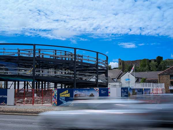
Externally, the overall scheme includes highway access improvements, a revised taxi rank, while adjacent to the ramp, a new public realm will be created.
Summing up, Councillor Paul Miller, Deputy Leader of Pembrokeshire County Council, says: ‘It’s great to see the transport interchange beginning to take shape, which is an important part of the wider Haverfordwest Masterplan.
“The steel structure is an incredible piece of engineering – that when complete – will deliver a much-needed, modern transport hub for the local community, improving connectivity and accessibility for residents and visitors alike.
“This significant regeneration scheme will be transformational for local people, offering improved access to bus, taxi and cycling facilities with excellent connectivity to the riverside, shopping centre and railway.”
Haverfordwest Public Transport Interchange is due to open in June 2026.
Beams with a camber
Haverfordwest Public Transport Interchange makes use of long-span composite steel beams which have been pre-cambered. Max Cooper of the SCI offers some thoughts on use of pre-camber in composite construction.
Pre-camber refers to the vertical curvature induced in a steel beam during fabrication, prior to delivery to site. Its purpose is to counteract the deflection of the steel beam under construction stage loads, primarily the weight of the wet concrete.
By offsetting this initial deflection, a properly cambered beam helps to ensure a more level finished floor, which can be helpful in meeting serviceability limit state criteria. This may permit the use of a lighter steel section than would otherwise have been possible. Pre-cambering can also be beneficial during the construction stage as it reduces the risk of concrete ‘ponding’, where excessive sagging of the beam can lead to an increased volume of concrete being poured at midspan, and with it a higher than anticipated dead load.
The amount of camber specified is typically ~80% of the calculated pre-composite dead load deflection. When specifying the amount of camber, designers should consider how the real-life span and end conditions of the beam vary from the analysis assumptions and adjust the camber accordingly. Specifying significantly higher cambers should be avoided, as fabrication tolerances or lower-than-expected beam deflections could result in an over-cambered beam, creating a permanent high point in the floor or a thinner-than-expected composite slab. It is important to note that camber is rarely intended to counteract deflection from superimposed dead loads; these loads are resisted by the composite section after the concrete has cured which will be far stiffer than the steel beam alone. Once calculated, the required mid-span camber must be clearly stated on the structural drawings.
Camber is most beneficial for long-span secondary beams where construction stage deflections are significant. A practical minimum specified camber of 20mm is often adopted, as smaller amounts offer limited benefit and can be difficult to achieve reliably through the cold-bending process.
It is also important to identify members where camber should not be used. Beams that directly support cladding, masonry, or other façade systems should not typically be cambered. This ensures a straight, level, and predictable datum for the attachment of façade elements, which often have tight installation tolerances. It is also recommended that camber is omitted from primary beams, as the use of camber for both primary and secondary beams can make fit-up more difficult.
Tolerances for cambered beams are governed by the National Structural Steelwork Specification for Building Construction (NSSS), which in turn references BS EN 1090-2. For a beam of span L, the specified tolerances are:
Negative tolerance: −Δ is the greater of L/1000or 4mm.
Positive tolerance: +Δ is the greater of L/500or 6mm.