Projects and Features
Floors with heavy loading – what are the implications?
In this article, Dr Graham Couchman considers the implications of high levels of loading, and how they can change expected failure modes and the design rules that should be applied. As usual, his focus is on composite floors, recognising their commercial significance to the UK steel construction sector.
Introduction
More-and-more clients are requiring their buildings to be designed for heavy imposed floor loads. A recent enquiry aimed at our Advisory Desk concerned a uniformly distributed load (UDL) of 22 kN/m²! We are also seeing many cases where there are heavy point loads (PL), often numerous and sometimes at close centres. Although in some cases these onerous loads are specified simply because the client wants to keep their options open to avoid delays while the real loads are determined, sometimes it seems the loads are realistic.
Heavy uniform loading
Many floors are designed for an unfactored UDL of 5 kN/m². In terms of what a typical floor will experience that is already pretty high, 2.5 kN/m² is recommended by the British Council for Offices, resulting in wasted money and wasted material. But for some types of building even 5 kN/m² is not enough, and that means that design rules and failure modes may change from what is normally used and expected. Some examples of things that may change are considered below.
Composite slabs
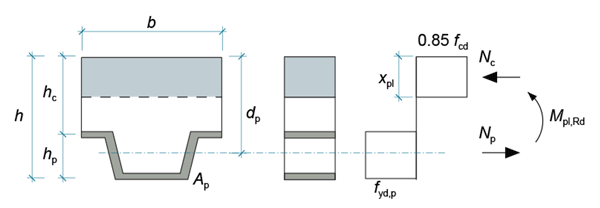
Design of the vast majority of composite slabs is governed by the ability of the decking to support the wet weight of concrete (and coincident construction stage imposed loads). The weight of concrete usually results from the need for a certain depth in order to satisfy the fire insulation criterion for the finished slab. Propping the decking to help it support the wet concrete is not normally considered because of the detrimental process implications of propping. However, with heavy final stage imposed loading the composite slab design may become more critical than the construction stage decking design, either at normal temperature or for the fire condition. The latter is likely to be particularly critical – decking losing almost all its resistance in fire is why, having ignored any end continuity for normal temperature design, we nevertheless take it into account in fire because the slab needs all the help it can get. Some sagging resistance comes from the very weakened deck, with a good lever arm, plus the more performant upper mesh with a small lever arm. The mesh is more performant because it is at a much lower temperature, being insulated by the concrete, so retains reasonable strength.
Even with the reduced level of loading that is associated with the fire limit state, this combination of sagging and hogging moment resistances may not be enough, particularly under high imposed load. In such cases, and in cases where there is no end continuity, therefore no hogging resistance, an obvious solution would be to place reinforcement bars in the decking troughs. These bars provide additional tensile resistance in span, with a good lever arm and relatively good strength as they are insulated by surrounding concrete. It is worth adding that some software may not allow bars and decking to be combined when determining tensile reinforcement and thereby sagging resistance. The so-called ‘mesh and deck’ method, which has a justification for the deck contribution that is based on tests, does not allow bars to act also.

Composite beams
Many composite beams are designed using the rules given in SCI publication P405 Minimum degree of shear connection rules for UK construction to Eurocode 4¹, which very significantly reduce the required minimum degree of shear connection compared to BS EN 1994-1-12. This reduction makes many designs that would not be possible – you simply cannot fit enough shear studs on the beam when you have transverse decking with ribs at a given pitch – very efficient. P405 rules are adopted in most composite beam software used in the UK.
The reason why we have minimum degree of connection rules is to ensure that the combined stiffness of the studs on a beam is enough to prevent the slip at the beam ends, where it is a maximum, exceeding the stud’s slip capacity. Slip capacity is typically taken as either 6mm, for studs in solid slabs, with parallel decking, or transverse re-entrant decking, or 10mm for transverse trapezoidal decking. This is therefore a strength check used to verify a stiffness requirement, and is not transparent.
The minimum degree of connection rules in P405 differentiate between levels of imposed loading. For normal cases the factored imposed UDL shall not exceed 9 kN/m². When loading is not just UDL, as an alternative this limit can be satisfied by limiting the moment due to factored imposed loading to 70% of the moment due to factored total loading. More onerous rules are given to cover factored imposed loading up to 12 kN/m², which is defined in P405 as ‘heavy loading’.
As an example, for a 16m span symmetric beam with transverse trapezoidal decking (studs have a slip capacity of 10mm), in S355 and assuming the beam is fully utilised in bending, the minimum degree of connection is:
- Normal loading 43%
- Heavy loading 91%
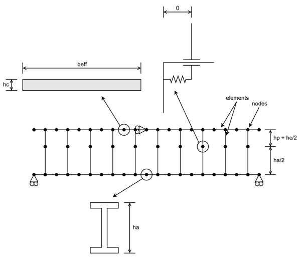
The reason for this differentiation in the level of imposed loading can be understood by considering the background to the rules. Numerical analyses were undertaken by SCI, using ANSYS to model composite beams with springs representing appropriately defined load-slip characteristics for the shear studs – initial stiffness, resistance, slip capacity (Figure 2). For a given beam the number of studs was increased until the end slip no longer exceeded the slip capacity, then that number of studs was defined as a degree of shear connection. By analysing multiple beams, and considering different slip capacities for studs it was possible to define new degree of shear connection rules as a function of span, steel strength, slip capacity etc. An additional variable for unpropped beams was the relative level of imposed load.

Two phenomena differentiate how an unpropped beam behaves compared to a propped beam. Phenomenon 1 is that, self-weight has no impact on the shear studs – the fluid concrete merely ‘runs’ around them. Only the imposed loads result in forces applied to the studs, transferred via the now hard concrete, as the beam deflects. The relative level of dead to imposed loads, as well as the total load, is therefore important as it affects how much the studs will slip, so it can be readily seen how relative load levels will affect the minimum degree of connection that is needed. A complication, which is why numerical analysis is needed to model beams, is Phenomenon 2. The steel beam experiences higher strains under self-weight when unpropped compared to the same section when propped, because a composite beam typically has over twice the stiffness of the steel beam it is based on. The lower stiffness of the (bare steel) beam in an unpropped situation results in greater deflection and curvature, which means the extreme fibres get closer to their elastic limit under self-weight. When imposed loading is subsequently applied to the composite beam some of the steel then goes beyond its elastic limit (i.e. loses stiffness) ‘sooner’, deflections are greater as is end slip. This partly counters the lower slip due to Phenomenon 1.
The example numbers given above – 43% versus 91% – show how sensitive the required minimum degree is to the level of imposed loading. It is therefore very important that the P405 rules are not used out of scope, as they would be with a factored imposed load over 12 kN/m² (unfactored in excess of say 8 kN/m²).
BS EN 1994-1-1 gives rules for minimum degree of connection in 6.6.1.2. They do not distinguish between propped and unpropped construction, which means that the ratio of dead to imposed load is irrelevant (they cover the worst case where all loads are assumed to have an impact on the shear studs – i.e. propped construction). These rules may therefore be used for any level of imposed load, although care should always be taken when applying codified rules to very unusual situations as the rules may be based on tests and/or experience that were not representative of the situation actually being designed. Note this does not mean that the stud resistances from BS EN 1994-1-1 may also be used – they have been shown by test to be inaccurate and indeed unconservative when there are two studs per trough.
Unlike its predecessor, Generation 2 EN 1994-1-13, 8.6.3.3 does distinguish between propped and unpropped construction by using a variable kup to adjust the minimum degree of shear connection that is required. This variable has a value of 1.0 for propped, and can could drop to 0.85 at its extreme for unpropped. There is no mention of the relative level of dead to imposed loading, but as the benefit of unpropped is limited to only a 15% reduction in minimum degree, getting it right is a much less significant problem than when P405 rules are used.
Heavy and numerous point loads
The subject of heavy and/or numerous point loads has been covered in several recent articles and AD Notes from SCI. Heavy PLs place onerous requirements on a slab in terms of the transverse bending they cause, and the ability of what may be a relatively narrow strip of slab to support them4,5. Loads near a support, for example caused by a MEWP, tend to push the slab’s vertical shear resistance to the limit. Local punching through the slab, which is normally never critical, may also be a concern.
Because composite slabs are designed as one-way spanning, the biggest danger with numerous PLs may be that a designer does not appreciate all the loading that will be present on the 1m wide strip being designed6. A PL placed near centre span may well mobilise a strip of slab that is greater than 1m wide, and if it is sufficiently close (transversely) to another PL they could interact and both need to be considered when determining the input loads. The designer should take care to consider loads near to, not just centred on the line of, the strip being designed.
Conclusions
Experienced designers can often judge whether a design output feels right or not, based on their past experience. For example, anyone familiar with composite slab design will know that the ability of the steel decking to support the wet weight of concrete governs slab design most of the time. However, self-evidently when faced with an unusual situation past experience loses some of its value. In this article we have considered how the current demands from numerous clients to considered heavier floor loads than have been typical, and multiple point loads on some floors, can affect key aspects of composite floor design.
References
- P405 Minimum degree of shear connection rules for UK construction to Eurocode 4, SCI, 2015
- BS EN 1994-1-1:2005, Eurocode 4 – Design of composite steel and concrete structures – Part 1-1: General rules and rules for buildings, BSI, 2005
- Fpr EN 1994-1-1:2025, Eurocode 4 – Design of composite steel and concrete structures – Part 1-1: General rules and rules for buildings, CEN, Unpublished
- AD450 Resistance of composite slabs to concentrated loads, SCI, 2020
- AD477 Transverse bending of composite slabs subjected to point loads. SCI, 2021
- Dealing with multiple point loads on a composite slab. NSC Nov/Dec 2024


