50 & 20 Years Ago
Modern Steel Bridges
From Building with Steel
NOVEMBER 1960
RUNCORN-WIDNES BRIDGE
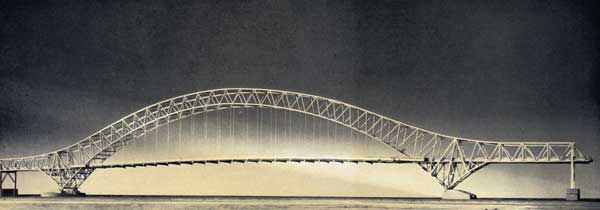
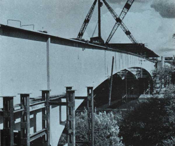
The new Runcorn-Widnes Bridge is of the arched design and has a central span of 1,082 ft. with side spans of 250 ft. The bridge is approached by reinforced concrete viaducts on each side of the river. The bridge provides for a 33-ft. carriageway and two 6-ft. footpaths.
The foundation work consists of a large skew pier in the river on the Widnes side, a skew pier on the Runcorn side, two approach piers in Widnes and foundation work for the side spans of the arch bridge.
A large amount of property has had to be acquired in connection with the approaches and the total estimated cost of the works and property is of the order of £2,900,000.
The total weight of steel in the main bridge is approximately 5,600 tons, and includes mild steel to B.S. 15, high-tensile steel to B.S. 548, and weldable high-tensile steel to B.S. 968.
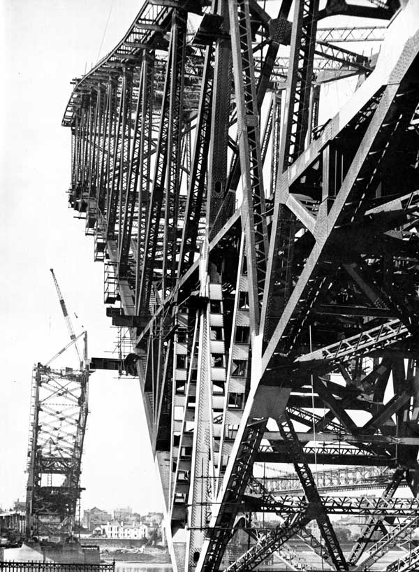
The rise of the arch is 252 ft. 6 in. above the bearings, the main arch ribs are placed at 54 ft. centres at varying depths from 35 ft. to 95 ft. approximately, the truss cords being generally 33 in. × 27 in. enclosed box section. Hangers of locked coil steel wire rope will be suspended from the arch rib to support the deck of the bridge. The deck is constructed of welded steel cross girders and stringers with reinforced concrete deck.
A feature of the design of the bridge viaducts are the ‘T’ shaped piers that support the reinforced concrete beams which in turn take the reinforced concrete deck.
It is anticipated that the work will be completed in the spring of 1961.
Consulting Engineers Mott, Hay & Anderson, London, S.W.1.
MAIDENHEAD BRIDGE
Maidenhead Bridge, now under construction for the Ministry of Transport, will carry the new West of Slough-West of Maidenhead motor road across the River Thames a mile and a half south of Maidenhead.
The foundations and abutments of the bridge were substantially completed in 1940, after which work was suspended. When work was resumed in 1958 the opportunity was taken by Freeman, Fox & Partners, the consulting engineers, of re-designing the superstructure to take advantage of higher working stresses and modern fabrication methods. In particular, extensive use has been made of shop-welded and site-welded high tensile steels.
The bridge will carry two carriageways each 24 ft. wide, two 6 ft. wide cycle tracks and two footpaths each 5 ft. 6 in. wide. The carriageways have 1 ft. marginal strips along each edge and are separated by a 13 ft. wide central reservation. The cycle tracks are separated from the carriageways by 6 ft. wide verges accommodating unclimbable fencing and guard rails. The overall width of the bridge deck is approximately 100 ft. Substantial steel parapets are provided on each side of the bridge.

The bridge has a central span of 270 ft. and two side spans, each of 38 ft. The superstructure consists of eight all-welded high-tensile steel girders, continuous over the supports and anchored at their extremities inside the abutments by means of hinged steel tension links. The girders are interconnected by welded mild steel cross frames bolted in position using high-strength friction grip bolts. The deck consists of an 8½ in. thick reinforced concrete slab cast in situ on top of the upper flanges of the main girders and made to act in combination with them by the provision of suitable shear connectors welded at intervals along their length. The slab is continuous between abutments, expansion joints being provided at each end. The slab is waterproofed throughout by means of mastic asphalt.
Work at site recommenced in January, 1960, and is expected to be completed in December, 1960.
Consulting Engineers Freeman, Fox & Partners, London, S.W.1.
KINGSFERRY BRIDGE
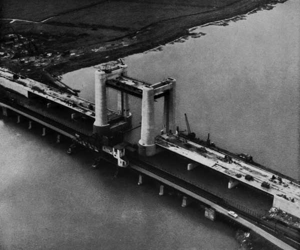
The new Kingsferry Bridge is intended to replace the existing combined river and road bridge, and provides for an increased width for navigation, the old bridge allowing for only 57 ft., the new one having 90 ft. Furthermore, the new bridge provides for a 24-ft. carriageway and 6-ft. footpath, and a single line of railway, as against a single carriageway and single railway track on the old bridge.
After considering various possibilities for the new bridge this vertical lifting type was adopted. The British Transport Commission obtained powers in 1957 for carrying out the new construction work and the work was put in hand at the end of that year.
The new lifting bridge is 50 ft. wide and has been designed so as to provide for a vertical opening 95 ft. clear above high water. The lifting span and the side spans are all constructed in steelwork with reinforced concrete decking. A feature of the bridge is the reinforced concrete towers which house the counterweights, sheaves and bridge control room. These towers rise to 130 ft. above the surrounding marshland and form a landmark which can be seen for many miles. The lifting span which rises vertically between towers weighs 465 tons and is counterweighted by four 110 ton counterweights. For services an 8 ft. 6 in. diameter tunnel connects the main pier foundations. The main piers are approached on each side by three side spans, each about 80 ft. The abutments on each side of the river are hollow reinforced concrete boxes resting throughout on concrete piles because of the very poor ground conditions adjacent to the river.
The cost of the works will be slightly over £i,ooo,ooo.
Consulting Engineers Mott, Hay & Anderson, London, S.W.1.
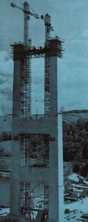
TAMAR BRIDGE
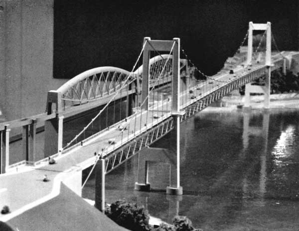
This bridge is of the suspension type and has a central span of 1,100 ft. and side spans of 374 ft. and provides for a carriageway 33 ft. wide, with two 6-ft. footpaths.
Approximately 1,000 tons of steel wire will be used in the main cables and suspenders and 3,000 tons of fabricated steelwork in the suspended structure.
The main river foundations are on twin caissons at each side of the river, and these have been founded on solid rock. On these piers the main towers of the bridge are being constructed and at the time of writing are almost completed. These will have a height of about 250 ft. The side towers, also of reinforced concrete, have been constructed on each side of the river, as also have anchorage tunnels which are provided to anchor the main cables of the bridge. The main cables each consist of 31 locked coil wire ropes of 2.37 in. diameter. The ropes will be entirely prefabricated and sockets will be attached to the ends at the works. These sockets will be connected to anchor rods at the anchorage tunnels. The 31 strands in each of these main cables will ultimately be surrounded by a protection of wire, so as to prevent seepage of water and corrosion. From these main cables hangers will be suspended which will support the stiffening . .truss. This in turn supports the reinforced concrete deck of the bridge. Work commenced at site in July, 1959: it is planned to complete the work in the summer of 1961.
The estimated cost of the bridge is approximately £1,500,000.
Consulting Engineers Mott, Hay & Anderson, London, S.W.1.