50 & 20 Years Ago
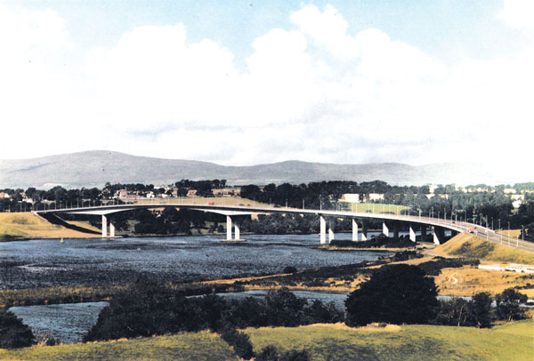
Foyle Bridge, Londonderry, Northern Ireland
For The Department of the Environment for Northern Ireland
AWARD
SSDA 1985
Structural Engineers:
Freeman Fox & Partners in association with RDL-Graham Joint Venture
Steelwork Contractors:
RDL-Graham Joint Venture
Steelwork Fabricators:
Harland & Wolff plc
Foyle Bridge was constructed under a ‘design & build’ contract and was the second major bridge in the United Kingdom to be built thus in recent years. The design brief, issued by the client to prequalified contractors, was not unduly restrictive but the navigational clearances required and the presence of geological faulting dictated a main river span of such length that steel was the preferred medium. The brief cited aesthetic quality and low vulnerability to damage as two factors to which importance was attached.
The bridge carries dual two-lane carriageways and footways across the River Foyle about 2km north of Londonderry in Northern Ireland. With its concrete approach viaduct the bridge has a total length of 866m, of which the three steel spans over the river account for 522m. The main span is 234m long and is flanked by two side spans of 144m. The steel spans have an orthotropic deck carried on twin box girders of varying depth. For security reasons the bridge is divided along the median into two separate structures. The steelwork is shop welded and site bolted wherever possible. The exception is the deck plate itself which had to be site jointed by welding as the asphalt surfacing could not provide sufficient cover to bolt heads.
The design of the steelwork complies with the Merrison Interim Design and Workmanship Rules and consequent on the completion of BS.5400 (Steel, concrete and composite bridges) Foyle Bridge is probably the last bridge to be designed to those Rules.
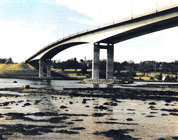
The orthotropic steel deck plate, between 13mm and 16mm thick, is stiffened with cold-rolled Vtroughs 8mm thick: fabricated cross girders are at 3.6m centres. The 10mm thick web plates are stiffened with horizontal bulb-flats and angles and with vertical T-stiffeners. The heavy bottom flange plates are stiffened with universal flat plate stiffeners. The steel spans are designed so that in the full dead-load condition there is a theoretical zero bending moment at the centre of the main span. The two girders are anchored laterally and longitudinally to the west abutment, fixed by pin bearings to the two main piers and free to move longitudinally on roller bearings on top of Pier 3 at the interface with the concrete viaduct. The main pier-shafts are designed to bend with thermal and live load movements of the steel girders. Changes in the overall length of the steel spans and the western half of the viaduct are taken up at the main expansion joint above Pier 3.
The design process was closely related to the erection scheme simultaneously being developed by the contractor, an obvious advantage of ‘design and construct’ procedures. The contractor decided to have the steelwork fabricated in very large sections, weighing about 950 tonnes, in Belfast and to tow these to the site on sea-going barges thus drastically reducing assembly work at the site. The method had a pronounced effect on the stresses generated in the structure and led to the development of predesigned jacking procedures to modify the moments and shears.
Use of the big-lift scheme meant that erection work was reduced to a simple sequence of major events in taking the six girder units from Belfast to site, placing each one in position, and splicing the three units in each girder to the required shape and condition. The sequence was as follows:
- Transport to site and off load each of four side span units.
- Lift and traverse each side span unit to its correct position
- In preparation for lift of centre span units raise the extreme ends of all four side span units 6.5m above bearing level.
- Transport two centre span units to site and lift off barge into position between side span units.
- Complete four field splices and lower extreme ends of girders on to bearings establishing designed bending moment distribution in each completed girder.
The protective treatment was required to provide a minimum of 12 years durability and the principal systems used were zinc metal spray for the deck plate, 5 coats of chlorinated rubber for the external surfaces and 3 coats zinc phosphate epoxy ester for internal surfaces.
Much attention was given, at tender stage and in detailing, to produce a bridge which would harmonise with the site and this has been effectively realised.
The design for submission by the consortium to the client commenced in 1978, work starting on site in December 1980. The 5,200t of steel were delivered to site and erected in less than 12 months and both carriageways were open to traffic by July 1984. The total cost of the scheme was £22 million.
Judges’ Comments
This is an excellent example of the use of steel to produce an aesthetically pleasing, light yet robust major steel bridge. It has benefited greatly fro he cross fertilisation between bridge and ship building, both in detail and construction.