Technical
NSC 29
Nov/Dec 18
only small changes in the neutral axis are expected, as a small increase in
the assumed slab depth increases considerably the slab resistance.
3. For assessing the resistance of the slab, generally no reduction in strength
is needed (ambient temperature may be assumed). An alternative often
used, which is to assume the slab temperature is equal to 40% of the steel
top flange temperature (a rule used to assess studs resistance under fire),
can be seen as a conservative solution.
References
1 BS 5950-8:2003
Structural use of steelwork in building - Part 8: Code of practice for fire
resistant design
BSI, 2003
2 BS EN 1994-1-1:2004
Eurocode 4 - Design of composite steel and concrete structures - Part 1-1:
General rules and rules for buildings
BSI, 2005
3 BS EN 1994-1-2:2005+A1:2014
Eurocode 4 - Design of composite steel and concrete structures - Part 1-2:
General rules - Structural fire design
BSI, 2005
4 NA to BS EN 1994-1-2:2005
UK National Annex to Eurocode 4: Design of composite steel and concrete
structures - Part 1-2: General rules - Structural fire design
BSI, 2008;
5 PN005c-GB
NCCI: Fire resistance design of composite slabs
The Steel Construction Institute
6 Steel and composite structures: behaviour and design for fire safety
Y. C. Wang, Spoon Press, 2005
7 AS/NZ 2327.1
Composite Structures – Composite steel-concrete construction in buildings
Standards Australia/Standards New Zealand, 2017
Mpl,rd,fire
kNm
Slab temperature profile case
η 1 2 3 4 5 6 7 8
0.00 37.71 37.71 37.71 37.71 37.71 37.71 37.71 37.71
0.25 60.22 60.22 60.22 60.22 60.22 60.22 60.22 60.22
0.50 76.24 76.24 76.24 76.24 76.24 76.24 76.24 76.24
0.75 91.41 91.41 91.41 91.41 91.35 91.30 91.36 91.34
1.00 105.37 105.25 105.25 105.08 105.00 104.95 105.01 104.99
Mpl,rd,fire
kNm
Slab temperature profile case
η 1 2 3 4 5 6 7 8
0.00 199.13 199.13 199.13 199.13 199.13 199.13 199.13 199.13
0.25 284.60 284.60 284.60 284.60 284.60 284.60 284.60 284.60
0.50 335.08 335.08 335.08 335.08 335.08 335.08 335.08 335.08
0.75 375.67 375.44 375.44 375.10 374.93 374.82 374.95 374.92
1.00 413.06 412.83 412.83 412.49 412.33 412.22 412.34 412.31
Table 4 – Results for 6 m span beam: UB 203 x 133 x 25; Steel critical temperature: 621°C. Table 5 – Results for 12 m span beam: UB 406 x 178 x 67; Steel critical temperature: 620°C
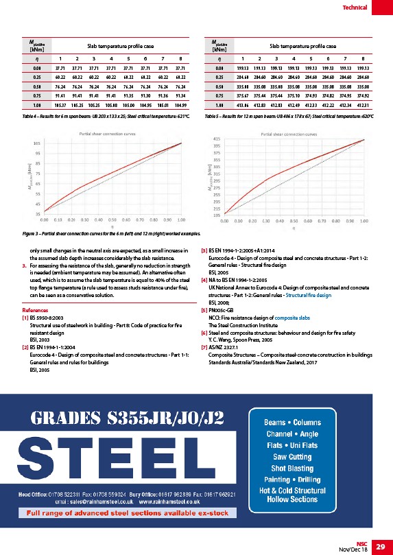
Figure 3 – Partial shear connection curves for the 6 m (left) and 12 m (right) worked examples.
/Design_using_structural_fire_standards
/Floor_systems#Composite_slabs
/www.rainhamsteel.co.uk
link