Commercial
19
internal diagonals.
The internal diagonals are installed with
the bolts pinned in oversized holes to allow
movement in the truss when the building
deflects with axial shortening under gravity
loads during construction. These do not
become ‘active’ until the building is fully
loaded, at which point they will be tightened.
The trusses vary in size depending on their
locations, with the largest fully assembled
truss measuring approximately 15m × 7.6m.
“The booms were brought to site with
complex, offset and heavy node connections
on transport frames. They were designed and
fabricated by ourselves to be lifted straight in
to their as-built position from the back of the
trailer,” says Mr Fletcher.
As there are outrigger sections embedded
within the concrete core, steelwork contractor
Severfield had to design, fabricate and deliver
these elements well in advance of the main
steelwork.
Once the steelwork and floors were
installed up to levels 25 and then 41, the
V-shaped trusses were installed either side of
the core and connected to plates left exposed
from the elements inside the concrete core.
Twentytwo is due to complete by the end
of 2019.
Outriggers The lateral stiffness of 22 Bishopsgate is increased in the direction of the narrow dimension of the concrete
core by mobilising the perimeter columns. Richard Henderson of the SCI discusses some of the issues.
The lateral stiffness of a building with
columns by means of stiff beams known
as outriggers. In 22 Bishopsgate these are
provided at two levels and are double storeyheight
moment in the building core increases rapidly
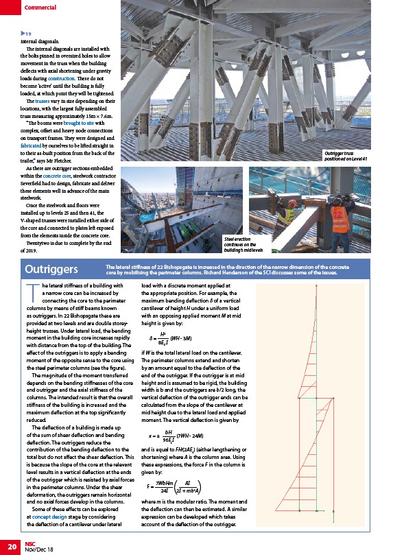
with distance from the top of the building. The
effect of the outriggers is to apply a bending
moment of the opposite sense to the core using
the steel perimeter columns (see the figure).
The magnitude of the moment transferred
depends on the bending stiffnesses of the core
and outrigger and the axial stiffness of the
columns. The intended result is that the overall
stiffness of the building is increased and the
maximum deflection at the top significantly
reduced.
The deflection of a building is made up
of the sum of shear deflection and bending
deflection. The outriggers reduce the
contribution of the bending deflection to the
total but do not affect the shear deflection. This
is because the slope of the core at the relevant
level results in a vertical deflection at the ends
of the outrigger which is resisted by axial forces
in the perimeter columns. Under the shear
deformation, the outriggers remain horizontal
and no axial forces develop in the columns.
Some of these effects can be explored
at concept design stage by considering
the deflection of a cantilever under lateral
20 NSC
a narrow core can be increased by
connecting the core to the perimeter
trusses. Under lateral load, the bending
Nov/Dec 18
load with a discrete moment applied at
the appropriate position. For example, the
maximum bending deflection δ of a vertical
cantilever of height H under a uniform load
with an opposing applied moment M at mid
height is given by:
H2
δ =
(WH - 3M)
8EC I
if W is the total lateral load on the cantilever.
The perimeter columns extend and shorten
by an amount equal to the deflection of the
end of the outrigger. If the outrigger is at mid
height and is assumed to be rigid, the building
width is b and the outriggers are b/2 long, the
vertical deflection of the outrigger ends can be
calculated from the slope of the cantilever at
mid height due to the lateral load and applied
moment. The vertical deflection is given by
bH
96EcI
x = ± (7WH - 24M)
and is equal to FH⁄(2AEs) (either lengthening or
shortening) where A is the column area. Using
these expressions, the force F in the column is
given by:
7WbHm
F = ( AI
)
24I
2I + mb2A where m is the modular ratio. The moment and
the deflection can then be estimated. A similar
expression can be developed which takes
account of the deflection of the outrigger.
Outrigger truss
positioned on Level 41
Steel erection
continues on the
building’s mid levels
/Construction
/Trusses
/Fabrication#Handling_and_transportation
/Fabrication
/Concept_design#Concrete_or_steel_cores
/Concept_design