Technical
lightweight concrete and h1 ≥ 80 mm for normal weight concrete.
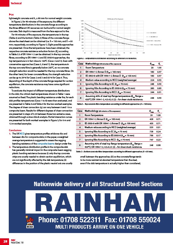
In Figure 2, for 90 minutes of fire exposure, the different
temperature distributions in the concrete flange according to
the three different UK resources can be found for normal weight
concrete. Slab depth is measured from the face exposed to fire.
For 90 minutes of fire exposure, the temperatures in the top
(Table 2) and the bottom (Table 3) fibres of the concrete flange
above the steel sheet can be obtained (i.e. X = 130 mm, and X = 60
mm, respectively, according to Figure 1). Eight possible approaches
are presented. Once the temperatures have been obtained, the
respective concrete resistance reduction factors (Kc) according
to Table 3.3 of EN 1994-1-2 can be obtained. In the top concrete
fibres, according to EN 1994-1-2 and BS 5950-8 approaches, the
top temperature is in fact close to 140°C (Cases 2 and 3). Even with
conservative approaches (Cases 5, 6 and 7), the temperature in
the top concrete fibre is generally below 250°C, so no concrete
strength reduction would be needed for the top concrete fibres. On
the other hand, for lower concrete fibres, the strength reduction
can be up to 29 % for Cases 2 and 3 and 83 % for Case 6. Thus,
depending of the depth of the concrete flange required for section
equilibrium, the concrete resistance may have some significant
reductions.
To evaluate the impact of different temperature distributions
in the slab, the critical steel temperatures shown in Table 1 were
assumed as fixed. The plastic bending resistance under fire, for each
slab profiles temperatures (Cases 1 to 8) were then evaluated, and
are presented in Table 4 and Table 5 for the two worked examples.
The degree of shear connection (η) can vary between 0 and 1 in a
composite beam. Results for different degrees of shear connection
are presented in steps of 0.25 between those two extreme cases,
obtained through a stress block analysis. Partial interaction curves
are presented for both worked examples in Figure 3, for 6 m and
12 m worked examples.
Conclusions
1. The UK NCCI gives temperature profiles at/above ribs and
between ribs for composite slabs; in the paper, a weighted
average temperature is suggested to assess the sagging
bending resistance of the composite beams design under fire.
2. The temperature distribution profile in the composite slab
has generally minimal impact in the composite beam sagging
plastic bending resistance because: (i) only the top concrete
strips are usually needed to obtain section equilibrium, which
are not significantly affected by the slab temperature; (ii)
differences in the position of the plastic neutral axis are usually
28 NSC
Nov/Dec 18
small between the approaches; (iii) as the concrete flange tends
to be more resistant at elevated temperature than the steel,
even if the slab temperature is actually higher than considered,
26
Figure 2 - Temperature distribution according to different UK resources.
Case Methodology (90 minutes of fire exposure) θc,top Kc
1 Room Temperature 20 1.00
2 EN 1994-1-2 Annex D (heff = 100 mm) 160 0.97
3 BS 5950-8 with EN 1994-1-2 Annex D (heff ≥ 100 mm) 160 0.97
4 Medium value according to NCCI (weighted average) 224 0.93
5 Ignoring Ribs According to EC (heff = 70 mm) 246 0.90
6 Ignoring Ribs According to BS 5950-8 (heff = 70 mm) 260 0.89
7 Ignoring Ribs According to NCCI (heff = 70 mm) 244 0.91
8
Assuming 40% of steel top flange temperature (θtop flange =
620°C) EN 1994-1-2, 4.3.4.2.5 (2) – for shear studs resistance.
248 0.90
Table 2 – Top concrete fibre temperature according to different approaches (X = 130 mm).
Case Methodology (90 minutes of fire exposure) θc,top Kc
1 Room Temperature 20 1.00
2 EN 1994-1-2 Annex D (heff = 100 mm) 428 0.71
3 BS 5950-8 with EN 1994-1-2 Annex D (heff ≥ 100 mm) 430 0.71
4 Medium value according to NCCI (weighted average) 559 0.51
5 Ignoring Ribs According to EC (heff = 70 mm) 738 0.24
6 Ignoring Ribs According to BS 5950-8 (heff = 70 mm) 790 0.17
7 Ignoring Ribs According to NCCI (heff = 70 mm) 747 0.23
8
Assuming 40% of steel top flange temperature (θtop flange =
620°C) EN 1994-1-2, 4.3.4.2.5 (2) – for shear studs resistance.
248 0.90
Table 3 – Bottom concrete fibre temperature according to different approaches (X = 60 mm).
/Design_codes_and_standards#NCCI
/Composite_construction#Types_of_composite_beam