Technical
NSC 27
Mar 20
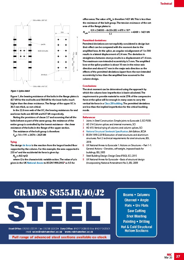
Figure 1, the bearing resistance of the bolts in the flange plates is
427 kN for the end bolts and 564 kN for the inner bolts: much
higher than the shear resistance. The flange of the upper UC is
36.5 mm thick, so not critical.
In the 22.6 mm web of the UC, the bearing resistances for end
and inner bolts are 483 kN and 637 kN respectively.
Noting the provisions of clause 3.7 and assuming that all the
bolts behave as part of the same group, the resistance of the
entire group is controlled by the lowest resistance – the shear
resistance of the bolts in the flange of the upper section.
The resistance of the bolt group is therefore:
FRd= 14 × 191 = 2674 > 2625 kN
Tying
The design tie force is the reaction from the largest loaded floor
supported by the column. For this example, the area supported is
233 m2 and the accidental tie force is given by:
NEd = A(G+ψQ)
where Q is the characteristic variable action. The value of ψ is
given in the UK National Annex to BS EN 1990:20028 as 0.5 for
office areas. The value of NEd is therefore 1421 kN. This is less than
the resistance of the bolt group. The tension resistance of the net
area of the flange plates is:
0.9 × (14000 – 4×33×20) × 470 × 10
NRd = = 4369 > 1421 kN
u,1.1
Permitted deviations
Permitted deviations are not explicitly considered in design but
their effect can be compared with the moment due to the
amplified bow. At the splice, an angular misalignment of 1 in 500
results in a lateral displacement of 2.4 mm. The deviation in
straightness between storeys results in a displacement of 1.6 mm.
The maximum non-intended eccentricity is 5 mm. The amplified
bow at the splice position is about 10 mm in the minor axis
direction and about 4.7 mm in the major axis direction so the
effects of the permitted deviations (apart from the non-intended
eccentricity) is less than the amplified bow assumed in the
column design.
Conclusions
The strut moment can be determined using the approach by
which the column bow imperfection is back-calculated. The
requirement to provide material to resist 25% of the compressive
force at the splice will be enough in many cases to carry the
vertical tie force in a Class 2B building. The permitted deviations
are less than the implied imperfection for the critical buckling
mode.
References
1 Joints in Steel Construction: Simple joints to Eurocode 3, SCI P358.
2 AD 314 Column splices and internal moments, SCI
3 AD 415: Vertical tying of columns and column splices, SCI
4 National Structural Steelwork Specification, 6th Edition, BCSA
5 BS EN 1090-2:2018 Execution of steel structures and aluminium
structures. Part 2: technical requirements for steel structures, BSI,
2018
6 UK National Annex to Eurocode 1: Actions on Structures – Part 1-1:
General Actions – Densities, self-weight, imposed loads for
buildings, BSI, 2005
7 Steel Building Design: Design Data (P363), SCI, 2015
8 UK National Annex for Eurocode – Basis of structural design
(Incorporating National Amendment No.1), BSI, 2009
Figure 1: Splice detail
/Structural_robustness#Vertical_ties
/Design_codes_and_standards#National_Annexes
/Structural_robustness#For_Class_2B_buildings
/Steelwork_specification#The_National_Structural_Steelwork_Specification_for_Building_Construction
link
/www.rainhamsteel.co.uk