NSC 13
Mar 20 a series of 16m-long rafters forming the
structure’s required column-free space. The
handling area includes a 13m-deep concrete
bunker and substructure on to which
steelwork, forming the upper part of the
building, sits.
The concrete substructure walls are up to
18m-high, and the steel columns then extend
the building up to its maximum height of
37m-high.
The handling area’s columns are spaced at
7m centres and support a series of 26m-long
box section trusses that form the roof and
a clear column-free space. The trusses are
tapered and measure 4m at their deepest
point.
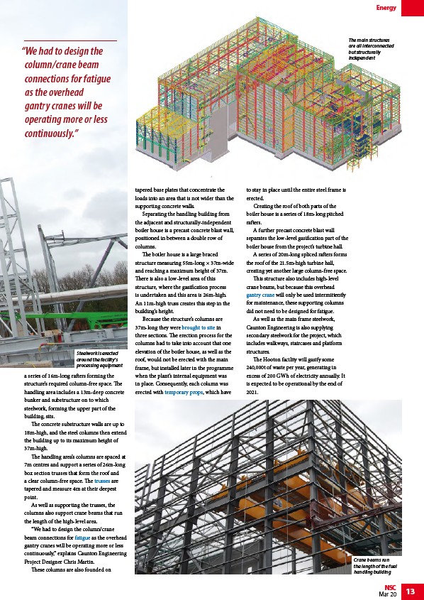
As well as supporting the trusses, the
columns also support crane beams that run
the length of the high-level area.
“We had to design the column/crane
beam connections for fatigue as the overhead
gantry cranes will be operating more or less
continuously,” explains Caunton Engineering
Project Designer Chris Martin.
These columns are also founded on
tapered base plates that concentrate the
loads into an area that is not wider than the
supporting concrete walls.
Separating the handling building from
the adjacent and structurally-independent
boiler house is a precast concrete blast wall,
positioned in between a double row of
columns.
The boiler house is a large braced
structure measuring 55m-long × 37m-wide
and reaching a maximum height of 37m.
There is also a low-level area of this
structure, where the gasification process
is undertaken and this area is 26m-high.
An 11m-high truss creates this step in the
building’s height.
Because the structure’s columns are
37m-long they were brought to site in
three sections. The erection process for the
columns had to take into account that one
elevation of the boiler house, as well as the
roof, would not be erected with the main
frame, but installed later in the programme
when the plant’s internal equipment was
in place. Consequently, each column was
erected with temporary props, which have
to stay in place until the entire steel frame is
erected.
Creating the roof of both parts of the
boiler house is a series of 18m-long pitched
rafters.
A further precast concrete blast wall
separates the low-level gasification part of the
boiler house from the project’s turbine hall.
A series of 20m-long spliced rafters forms
the roof of the 21.5m-high turbine hall,
creating yet another large column-free space.
This structure also includes high-level
crane beams, but because this overhead
gantry crane will only be used intermittently
for maintenance, these supporting columns
did not need to be designed for fatigue.
As well as the main frame steelwork,
Caunton Engineering is also supplying
secondary steelwork for the project, which
includes walkways, staircases and platform
structures.
The Hooton facility will gasify some
240,000t of waste per year, generating in
excess of 200 GWh of electricity annually. It
is expected to be operational by the end of
2021.
Energy
Steelwork is erected
around the facility's
processing equipment
The main structures
are all interconnected
but structurally
independent
Crane beams run
the length of the fuel
handling building
“We had to design the
column/crane beam
connections for fatigue
as the overhead
gantry cranes will be
operating more or less
continuously.”
/Trusses
/Fatigue_design_of_bridges#The_mechanism_of_fatigue
/Fabrication#Handling_and_transportation
/Construction#Temporary_works
/Portal_frames#Crane_actions