Commercial
The atrium has been
designed so that it can
be infilled if required
20 NSC
Mar 20
19 building’s services and these will also be
on show.
Because of the exposed nature of the
design, all of the cellular beam’s holes
are the same diameter, in order to give a
uniform appearance. In conjunction with
this, careful consideration has been given
to the appearance of all of the connections
and the orientation of the bolts, while a
basic specification of intumescent paint has
been applied offsite to all of the columns
and beams, then carefully touched-up on
site to give a consistent appearance.
The desire to have uniformity and visual
appeal within the steel frame has also
extended to the perimeter columns. Every
member is selected from the same family
of Universal Column sections to appear the
same size, unlike most other buildings were
sections usually decrease in size the further
up the structure they are.
Of the approximate 3,000 individual
steel elements on Building S1, the largest
is a 12m-long transfer structure, weighing
22t that facilitates a 6m setback in the
building above this level and helps to form
a 6m-wide, 39m long strip of terrace at the
7th floor level.
As a single piece this plate girder would
have been too heavy for either of the site’s
two tower cranes. Consequently, it was
brought to site in two pieces and spliced
together once the sections were in their
final position.
Building S1 is due to be complete by
February 2021.
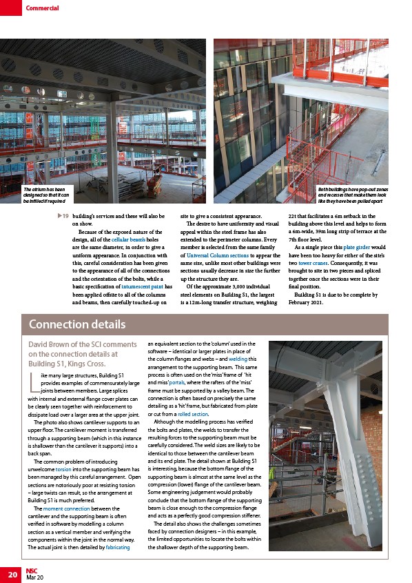
Like many large structures, Building S1
provides examples of commensurately large
joints between members. Large splices
with internal and external flange cover plates can
be clearly seen together with reinforcement to
dissipate load over a larger area at the upper joint.
The photo also shows cantilever supports to an
upper floor. The cantilever moment is transferred
through a supporting beam (which in this instance
is shallower than the cantilever it supports) into a
back span.
The common problem of introducing
unwelcome torsion into the supporting beam has
been managed by this careful arrangement. Open
sections are notoriously poor at resisting torsion
– large twists can result, so the arrangement at
Building S1 is much preferred.
The moment connection between the
cantilever and the supporting beam is often
verified in software by modelling a column
section as a vertical member and verifying the
components within the joint in the normal way.
The actual joint is then detailed by fabricating
an equivalent section to the ‘column’ used in the
software – identical or larger plates in place of
the column flanges and webs – and welding this
arrangement to the supporting beam. This same
process is often used on the ‘miss’ frame of ‘hit
and miss’ portals, where the rafters of the ‘miss’
frame must be supported by a valley beam. The
connection is often based on precisely the same
detailing as a ‘hit’ frame, but fabricated from plate
or cut from a rolled section.
Although the modelling process has verified
the bolts and plates, the welds to transfer the
resulting forces to the supporting beam must be
carefully considered. The weld sizes are likely to be
identical to those between the cantilever beam
and its end plate. The detail shown at Building S1
is interesting, because the bottom flange of the
supporting beam is almost at the same level as the
compression (lower) flange of the cantilever beam.
Some engineering judgement would probably
conclude that the bottom flange of the supporting
beam is close enough to the compression flange
and acts as a perfectly good compression stiffener.
The detail also shows the challenges sometimes
faced by connection designers – in this example,
the limited opportunities to locate the bolts within
the shallower depth of the supporting beam.
Connection details
David Brown of the SCI comments
on the connection details at
Building S1, Kings Cross.
Both buildings have pop-out zones
and recesses that make them look
like they have been pulled apart
/Steel_construction_products#Cellular_beams
/Fire_protecting_structural_steelwork#Intumescent_Coatings
/Steel_construction_products#Standard_open_sections
/Steel_construction_products#Plate_girders
/Construction#Tower_cranes
/Member_design#Torsion
/Moment_resisting_connections
/Fabrication
/Welding
/Portal_frames
/Steel_construction_products#Standard_open_sections