There has been a ferry across the River
Clyde between Erskine and Old Kilpatrick
for centuries but the density of traffic has
increased so much that one is now faced
either with a long queue at the ferry or with
a journey into Glasgow to use an alternative
crossing. A new scheme has been drawn up
linking the A8 (Glasgow-Gourock) and A82
(Glasgow-Inverness) trunk roads, costing over
£8M. Erskine Bridge is part of this scheme.
The bridge is a multi-span all-welded steel
box girder on single shaft concrete piers in
which the main span of 1,000ft will be the
longest cable-stayed span in the world. To
allow large ships such as the QE2 to continue
using the Clyde there will be a minimum
clearance of 180ft above HWOST.
Piers
The fourteen piers are all single diamond
shaped shafts of heights varying from 22
to 175ft. The shape was developed to give
a slender, graceful appearance and to offer
minimum wind resistance. The piers are
constructed of concrete and are designed
to flex longitudinally to accommodate
movements of the bridge due to temperature
changes.
Deck Structure
The total length of the bridge is 4,334ft,
comprising the main cable-stayed span of
30 NSC
Sept 19
Erskine Bridge
1,000ft, two anchor spans of 360ft, and twelve
approach spans, four on the south side and
eight on the north, generally of 224ft. The
total weight of steelwork involved is about
11,000 tons. All movement due to temperature
changes is accommodated by the rolling leaf
expansion joint in the deck between piers 7
and 8, and by a toothed deck joint and roller
bearings at both abutments.
The steel deck girder is of elegant aerodynamic
shape similar to those of the Severn and Wye
bridges. It is generally 10ft 7½in deep at the
centre with cantilevers on both sides to carry
cycle tracks and footways. The total width
varies from 102ft 6in at the main span, where
the central reservation is wider, to 97ft 6in
over the approach spans.
The supporting cables are 2½in diameter
wire strands arranged in groups anchored to
the steelwork in the central reservation and
passing over 125ft high tapering steel masts
of box section rising from the main piers.
The roadway surface is of mastic asphalt
affixed directly to the steel deck plate. Design
of the cycle tracks is such that they may be
used to extend the carriageway whenever the
expected increase in volume of traffic should
warrant a third lane. Four 24in diameter
water mains and two 12in diameter gas
mains will be carried below the footways
so that any maintenance on them will not
interrupt traffic flow.
Reprinted from Volume 5 No. 4
June 1969
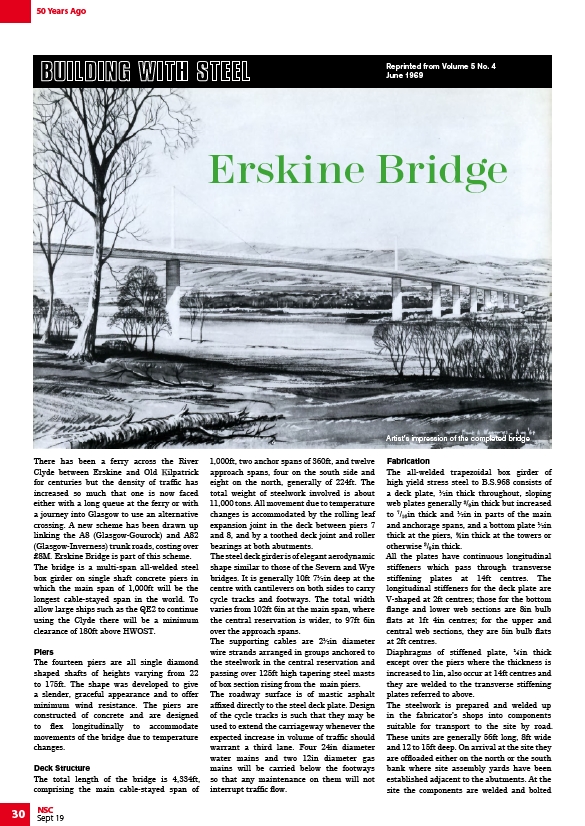
Artist's impression of the completed bridge
Fabrication
The all-welded trapezoidal box girder of
high yield stress steel to B.S.968 consists of
a deck plate, ½in thick throughout, sloping
web plates generally 3/8 in thick but increased
to 7/16 in thick and ½in in parts of the main
and anchorage spans, and a bottom plate ½in
thick at the piers, ¾in thick at the towers or
otherwise 3/8 in thick.
All the plates have continuous longitudinal
stiffeners which pass through transverse
stiffening plates at 14ft centres. The
longitudinal stiffeners for the deck plate are
V-shaped at 2ft centres; those for the bottom
flange and lower web sections are 8in bulb
flats at 1ft 4in centres; for the upper and
central web sections, they are 5in bulb flats
at 2ft centres.
Diaphragms of stiffened plate, ¼in thick
except over the piers where the thickness is
increased to 1in, also occur at 14ft centres and
they are welded to the transverse stiffening
plates referred to above.
The steelwork is prepared and welded up
in the fabricator’s shops into components
suitable for transport to the site by road.
These units are generally 56ft long, 8ft wide
and 12 to 15ft deep. On arrival at the site they
are offloaded either on the north or the south
bank where site assembly yards have been
established adjacent to the abutments. At the
site the components are welded and bolted
50 Years Ago