Technical
NSC 27
Sept 19
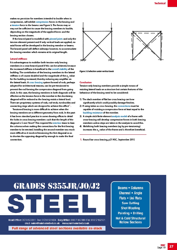
makes no provision for members intended to buckle when in
compression, will exhibit compression forces in the bracing and
a tension force in the beams: see Figure 3. The forces may or
may not be sufficient to cause the bracing members to buckle,
depending on the magnitude of the applied forces and the
bracing section chosen.
If the braced panel is modelled with pinned joints and only the
tension element present and if only vertical loads are applied, no
axial forces will be developed in the bracing member or beams.
The braced panel will deflect sideways however, to accommodate
the bracing member which remains at its original length.
Lateral stiffness
It is advantageous to mobilise both tension-only bracing
members in a cross-braced panel if this can be achieved, because
the increased stiffness is beneficial to the overall stability of the
building. The contribution of the bracing members to the lateral
stiffness is of course doubled and the magnitude of the αcr value
for the building increased, thereby reducing any amplifier on
the lateral loads. A cross bracing system formed of rods, perhaps
adopted for architectural reasons, can be pre-tensioned to
prevent the rod forming the compression diagonal from going
slack. In this case, the bracing members in both diagonals will be
effective as the tension force in the member in the shortening
diagonal will be reduced as the bracing resists a lateral load.
There are proprietary systems of rods, rod-ends, turnbuckles and
connecting rings which are designed to achieve this effect 1 .
Tensioned bracing is more difficult to achieve when the
bracing members are a different geometry from rods. In the past
it has been standard practice in some drawing offices to detail
the holes in cross bracing members such that the length of the
diagonal is 5 mm “short”. This required the erection team to lean
the columns when making the connections for the first bracing
member to be erected. Installing the second member was much
more difficult as it involved tensioning the first diagonal so as
to shorten the opposing diagonal by enough to make the final
connection.
Figure 3: Deflection under vertical loads
Conclusion
Tension-only bracing members provide a simple means of
resisting lateral loads on a structure but certain features of the
behaviour of the bracing need to be considered:
1) The slack member of flat bar cross bracing can bow
significantly which could possibly damage finishes.
2) If using tubes as cross bracing, the connections must be
capable of resisting a compression force at least equal to the
buckling resistance of the member.
3) A simple stick finite element analysis model of a frame with
cross-bracing will develop compression forces in both bracing
members unless steps are taken in the analysis to avoid this.
4) Mobilising both bracing members (eg by pre-tensioning)
increases the αcr value of the frame and is therefore beneficial.
1. Round bar cross bracing, p21 NSC, September 2015
/Member_design#Compression
/Member_design#Tension
/Simple_connections
/Concept_design#Structural_options_for_stability
/Braced_frames#Vertical_bracing
/Construction#Steel_erection
/Simple_connections#Bracing_connections
/Member_design#Buckling_resistance
/Modelling_and_analysis
/www.rainhamsteel.co.uk
link