Technical
26 NSC
Sept 19
where =
Afy
Ncr
1270 × 355
78420 , and the
= = 2.4
imperfection factor for an RHS = 0.21.
Substituting values in the formula for the initial bow gives:
e0 = 19.7 × 10
1270
× 0.21 × ( 2.4 – 0.2 ) = 7.16mm
The amplified bow at failure is
Ncr
Ncr - Nb,Rd
e0 = 11.48 × 7.16 82mm
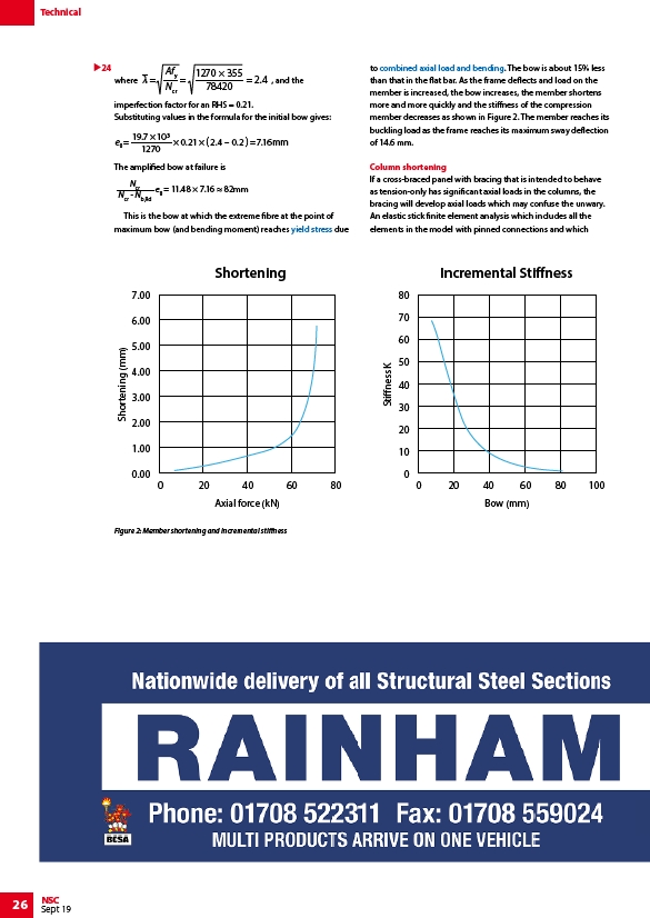
This is the bow at which the extreme fibre at the point of
maximum bow (and bending moment) reaches yield stress due
to combined axial load and bending. The bow is about 15% less
than that in the flat bar. As the frame deflects and load on the
member is increased, the bow increases, the member shortens
more and more quickly and the stiffness of the compression
member decreases as shown in Figure 2. The member reaches its
buckling load as the frame reaches its maximum sway deflection
of 14.6 mm.
Column shortening
If a cross-braced panel with bracing that is intended to behave
as tension-only has significant axial loads in the columns, the
bracing will develop axial loads which may confuse the unwary.
An elastic stick finite element analysis which includes all the
elements in the model with pinned connections and which
24
Shortening Incremental Stiness
7.00
6.00
5.00
4.00
3.00
2.00
1.00
0.00
Figure 2: Member shortening and incremental stiffness
80
70
60
50
40
30
20
10
0
0 20 40 60 80 0 20 40 60 80 100
Axial force (kN) Bow (mm)
Shortening (mm)
Stiness K
/Steel_material_properties#Yield_strength
/Member_design#Bending_and_axial_force