Technical
NSC 27
Feb 20
Joint stiffness
Joint classification boundaries on the basis of stiffness are given
in clause 5.2.2.5 and Figure 5.4 of BS EN 1993-1-8. The length of
the beam and some understanding of the overall frame stiffness
is needed, so some assumptions must be made. With reference to
Figure 5.4, assuming a 9 m long beam and kb = 8 (for frames with
bracing), the requirement for the rigid classification is then
Sj,ini ≥ kb EIb /Lb .
Substituting values, kb EIb /Lb = 8 × 210000 × 55200 × 104 ⁄ 9000
= 1.03 ×10¹¹ or 103 MNm/radian which is greater than the
stiffness calculated in section 2.0, unless μ = 1.0. This assessment
would therefore conclude that the joint can only be assumed to
be rigid if the design moment is 2/3 of the bending resistance of
the joint, or smaller. For unbraced “other frames” where the
beams are at least 10 times as stiff as the columns, kb = 25.
So for the rigid classification, the initial stiffness must be at least
322 MNm /radian so the joint would be classified as semi-rigid.
Effects of joint flexibility
BS EN 1993-1-1 clause 5.1.2(1) allows the analysis assumption of
perfectly pinned or perfectly rigid, as long as the real joint
behaviour does not have a ‘significant’ effect. As an illustration of
the effects of the joint stiffness, the same beam was modelled
using finite elements with rotational springs at the supports with
stiffness equal to the maximum value calculated. The model is
unrepresentative because no columns are included in the model.
A 9 m span beam is assumed with a uniform load of 41.1 kN/m,
giving a free bending moment of 416 kNm. The choice of load is
arbitrary. From classical beam theory, a beam with encastré ends
will have a support moment of 2/3 of the free bending moment
ie 277 kNm and a mid-span moment of 139 kNm. The mid-span
deflection will be 1/5 of the simply supported deflection,
calculated to be 30.5 mm due to bending alone (no shear
deflection). In a braced frame the joint detailed above can be
classified as rigid when carrying a design bending moment of
277 kNm or less.
The FE analysis results give a support moment of 130 kNm and
a mid-span moment of 286 kNm, with a maximum deflection
(including shear deflection) of 20.9 mm. The support moment is
about 47% of the encastré value and the deflection 3.4 times the
encastré value. The introduction into an analysis model of joint
stiffnesses calculated using BS EN 1993-1-8, although classified as
“rigid” clearly has a profound effect on the behaviour of the
structure and a decision to adopt a structural scheme that relied
on frame stiffness and bolted beam to column joints would need
to be considered carefully. The “wind-moment” method was
shown to be adequate by frame analysis incorporating
connection stiffness demonstrated by test, thus meeting the
requirements of the UK National Annex.
Traditional approaches to unbraced frame deflection
calculations have assumed that joints are rigid and deformation
of the members is the source of overall building deflections,
unless joints between members are of significant size relative to
the member lengths. Such assumptions may need to be
reconsidered for certain structures.
Conclusions
If joint stiffness is to be considered at all:
1) The manual calculation of stiffness is very laborious and it
would be unrealistic to try to design a real structure in this
way. Design software to calculate the joint stiffness is
essential for projects of any significant size.
2) The sequence of design and sizing is likely to be iterative
because the joint arrangements could affect both the
serviceability and strength limit states.
3) Flexibility of bolted end-plate joints in beam to column
connections in unbraced frame structures could have
significant effects on the stability of the structure.
1. Joints in steel construction: Moment-resisting joints to Eurocode 3
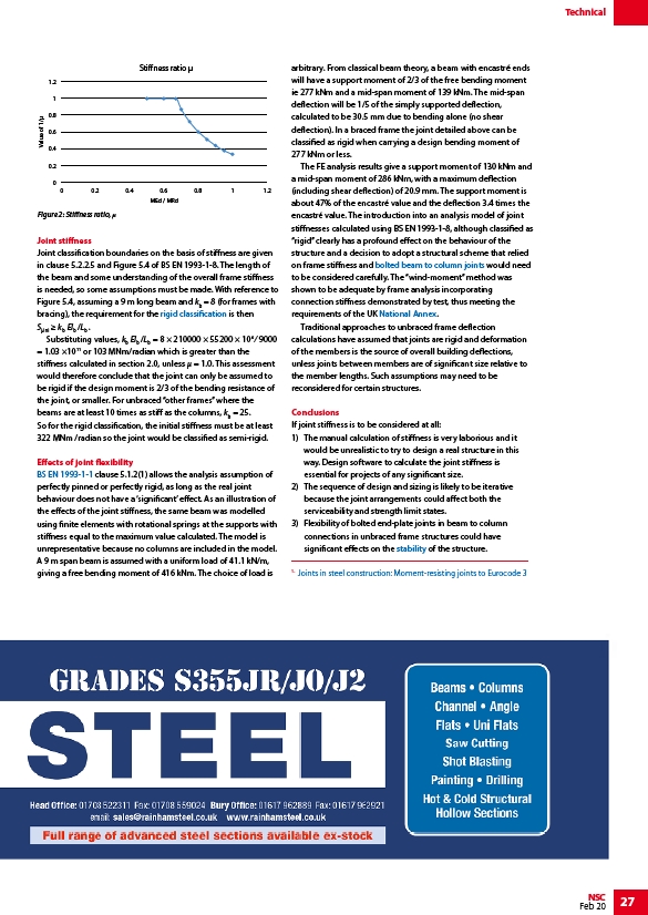
1.2
1
0.8
0.6
0.4
0.2
0
0 0.2 0.4 0.6 0.8 1 1.2
MEd / MRd
Value of 1/
Stiness ratio
Figure 2: Stiffness ratio, μ
/Moment_resisting_connections#Rigid_joint_classification
/Design_codes_and_standards#General_rules_and_rules_for_buildings
/Moment_resisting_connections#Bolted_beam-to-column_connections
/Design_codes_and_standards#National_Annexes
/Concept_design#Structural_options_for_stability
/The_Green_Books#Moment_resisting_connections
link
/www.rainhamsteel.co.uk