Technical
Joint stiffness calculation
The UK National Annex to BS EN 1993-1-8 discourages the use of numerical methods to
calculate joint stiffness, relying on previous satisfactory practice. Despite this, interest in joint
stiffness is increasing. Richard Henderson of the SCI illustrates the joint stiffness calculation
process set out in the standard and discusses some of the issues.
24 NSC
Feb 20
Introduction
Traditionally, the UK has relied on successful past practice to
classify orthodox connections – usually either nominally pinned
or nominally rigid. The UK National Annex to BS EN 1993-1-8
endorses that approach and discourages the use of the
numerical methods in the standard. The NA also indicates that
frame design methods which utilise semi-continuous connection
behaviour (the “wind-moment” method, for example) should not
use a numerically calculated value, but the connection behaviour
should be supported by test evidence or previous satisfactory
performance.
Designers are paying increasing attention to connection
stiffness, possibly because software is readily available
which makes the calculation possible even for unorthodox
arrangements. For a limited range of connections, BS EN 1993-1-8
presents a process to calculate the connection stiffness, utilising
the same basic connection components which are used to
calculate the moment resistance of the joint.
For designers not using software, this article demonstrates
the numerical approach given in the standard. The example
uses an existing connection design from P3981, where the basic
connection components are already established, shortening the
process.
Numerical example
Example C2 from the Green Book for moment connections, SCI
publication P398, has been used as a convenient bolted beam to
column connection to illustrate the method of calculating joint
stiffness. According to the UK National Annex to BS EN 1993-1-8,
this joint is nominally rigid, simply because it has been designed
in accordance with the Green Book.
The expression for the joint stiffness Sj is given in clause
6.3.1(4) as:
Sj = Ez
1
k
where: z is the lever arm defined in para 6.2.7 which depends on
the type of joint and the arrangement of the bolts;
μ is the stiffness ratio defined in para 6.3.1(6);
ki is the stiffness coefficient for basic joint component i.
The stiffness ratio, the ratio of the initial joint stiffness to the
stiffness under load, is unity if the applied joint moment Mj,Ed is
less than 2/3 of the joint resistance Mj,Rd. For higher moments, the
value of μ is given by:
μ = (1.5 Mj,Ed ⁄ Mj,Rd )ψ
The exponent ψ depends on the type of connection and is
given in Table 6.8.
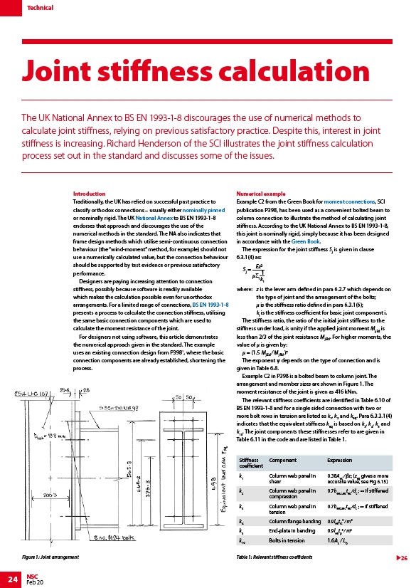
Example C2 in P398 is a bolted beam to column joint. The
arrangement and member sizes are shown in Figure 1. The
moment resistance of the joint is given as 416 kNm.
The relevant stiffness coefficients are identified in Table 6.10 of
BS EN 1993-1-8 and for a single sided connection with two or
more bolt rows in tension are listed as k1, k2 and keq. Para 6.3.3.1(4)
indicates that the equivalent stiffness keq is based on k3, k4, k5 and
k10. The joint components these stiffnesses refer to are given in
Table 6.11 in the code and are listed in Table 1.
Stiffness
coefficient
Component Expression
k1 Column web panel in
shear
0.38AVC ⁄ βz; (zeq gives a more
accurate value, see Fig 6.15)
k2 Column web panel in
compression
0.7beff,c,wctwc ⁄dc ; ∞ if stiffened
k3 Column web panel in
tension
0.7beff,t,wctwc ⁄dc ; ∞ if stiffened
k4 Column flange bending 0.9lefftfc
3 ⁄ m3
k5 End-plate in bending 0.9lefftp
3 ⁄ m3
k10 Bolts in tension 1.6As ⁄ Lb
Figure 1: Joint arrangement Table 1: Relevant stiffness coefficients
26
/Simple_connections
/Design_codes_and_standards#National_Annexes
/Design_codes_and_standards#Design_of_joints
/Moment_resisting_connections
/The_Green_Books#Moment_resisting_connections