Commercial
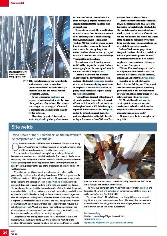
The Moorgate façade
will feature a sevenstorey
exposed truss
20 NSC
Feb 20
19 little room for manoeuvring the steelwork,
each node was placed on a trestle in a
position that allowed it to be lifted straight
from the truck and into its final position,”
explains Mr Loureiro.
As well as the arches, the trusses also
support columns along their width that form
the upper levels of the scheme. The columns
are arranged in a primary grid of 12m with
a secondary grid accommodating spans of
13.5m up to 21m.
Maximising the project’s footprint, the
eastern façade (along Moorgate) cantilevers
out over the Crossrail ticket office with a
seven-storey, fully-exposed perimeter truss
creating a signpost for the building’s main
entrance below.
The cantilever is created by a combination
of tripod supports from foundations inboard
of the perimeter, and a series of bowstring
trusses, measuring 25m-long and each
weighing 70t. The bowstring trusses are hung
from the east face truss over the Crossrail
station, while the building footprint is
further cantilevered at either end by a tripod
structure at the south-east corner and a large
V-frame at the north-east end.
The underside of the bowstring trusses
(soffit) will be lit up in the completed scheme,
drawing people into the building and towards
the main central full-height atrium.
Similar to many other steel elements
on the project, the bowstring trusses were
designed with the site’s tower crane capacities
in mind, and consequently they were detailed
as compound sections and fabricated in six
pieces, which were spliced together during
the erection programme.
“The east truss, like much of the structure’s
steelwork, has been designed to be lean and
efficient, with force paths reflected in the size
and weight of sections. All of the detailing is
expressed, as the entire truss will be exposed
and so the connections are all flush. The
nodes are also detailed to highlight the bolts
as they will be on show,” says WilkinsonEyre
Associate Director Melissa Clinch.
The tripod is fabricated from box sections
and, as the name suggests, it has three arms
that radiate outwards from its 10m-high top.
The base is founded on a concrete column,
which is positioned within the Crossrail ticket
hall and was designed and constructed as part
of the rail project’s package in preparation
for an over-site development, completing the
array of challenging site constraints.
Melissa Clinch says the project team
along with the client – Landsec – trialled an
enhanced procurement process, focussed
on collaboration to find the most suitable
suppliers to ensure maximum efficiency on
this complex development.
“William Hare were brought on board at
an early stage and this helped us work out
how each piece of steel could be fabricated,
detailed and, importantly, delivered to site.”
Summing up, Sir Robert McAlpine
Project Director Bob Kay says: “This project
demonstrates what is possible if you really
put your mind to it. The complexity of the
structure with limited points of support could
only be delivered with a steel frame.
“21 Moorfields could well prove to
be a template for numerous over-site
developments in London and shows that
they can be used to create some fantastic
architecture and valuable assets.”
21 Moorfields is due to be complete in
early 2021.
One of the themes at 21 Moorfields is the sense of magnitude. Long
spans, “mega” arches, with load focussed on a small number of piles
– a theme which continues with the connections.
The connections shown (in picture right) are very large site welds
between the members and the fabricated node. The plates on the faces are
temporary, used to align the members and hold them in position whilst the
welding is completed. Some appreciation of the very large welds can be
seen by looking closely at the size of the preparation on the members – the
welds are huge.
Welded details like this demand specialist expertise, which will be
provided by the Responsible Welding Coordinator (RWC), a required role for
CE Marked steelwork. Although these welds at 21 Moorfields are unusually
large, the same principles apply to all welds. Welding procedures will be
prepared, designed to avoid cracking in the weld and heat affected zone.
The weld procedures reflect the Carbon Equivalent Value (CEV) of the parent
material and the combined thickness at the weld, which is the total thickness
of material in each direction at the joint. More material means a larger heat
sink, allowing faster cooling, which increases the risk of cracking. Similarly,
a higher CEV increases the risk of cracking. The RWC will specify a welding
consumable with a particular hydrogen scale (less hydrogen reduces the
risk of cracking). The RWC will also specify the welding parameters – the
electrical parameters, consumable size and travel speed, which affect the
heat input – another variable to be carefully managed.
Designers will find the figures in BS EN 1011-2 educational and useful
background, as the figures relate CEV, hydrogen scale, heat input and
combined thickness to necessary preheat temperatures. Designers should
treat this as educational only – the responsibility lies with the RWC, for all
welds, not just the welds at 21 Moorfields.
The individual completing the welds will be appropriately qualified, and
for certain, the welds will be tested on completion. All of these issues are
addressed in Section 7 of BS EN 1090.
The site welds at 21 Moorfields are completely different in scale and
significance to the common 6 mm or 8 mm fillet welds, but demonstrate
that with careful thought, planning and expert input, even the large site
welds shown can be completed successfully.
Further reading
Guide to site welding (SCI publication P161)
SIGNS SN08, SN46
Typical welding procedures (BCSA publication 58/18)
Site welds
David Brown of the SCI comments on the site welds to
be completed at 21 Moorfields
/Trusses
/Facades_and_interfaces
/Steel-supported_glazed_facades_and_roofs#Atrium_Roofs_and_Sky_lights
/Construction#Tower_cranes
/Fabrication
/Construction#Steel_erection
/Visually_expressed_structural_forms
/Fabrication#Handling_and_transportation
/Braced_frames
/Construction#Site_welding
/Welding
/CE_marking
/Welding#Weld_procedure_specifications
/Welding#Hydrogen_cracking
/Welding#Welder_qualification
/Welding#Inspection_and_testing
/SIGNS-SN08.pdf
/SIGNS-SN46.pdf
/